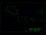
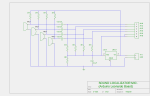
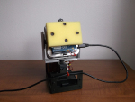
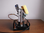
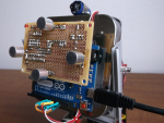
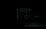
Well, it’s elementary simple in theory, how to do sound localization based on phase difference of signals, that received by two spatially distant microphones. The Devil, as always, in details. I’ve not seen any such project created for arduino, and get curious if it’s possible at all. Long story short, here I’d like to present my project, which answer this question – YES! Let me stress, project based on phase delay, not TDOA. Measurements results show, that current version of software (both copy of the source code, linked below, they differ only in filtering technics) has minimum detectable phase offset 1 degree!!!  This gives astonishing special resolution. For example, 10 kHz sound wave has length in the air about 34 millimeters, and if I divide it by 360 degree – full period, I’d get about 0.1 millimeters per 1 degree of phase shift.. Of course, as object getting away from the microphones, accuracy would proportionally deteriorate. What important is a ratio between distance to the object and distance between two mic’s (base). Having the base equals to 65 millimeters, device you can see in the video, capable detect location along horizontal line with accuracy 1 meter at distance 650 meters. Theoretically. Moreover, quantity of electronics components not much differs from what I’ve used in my previous blog. Compare two drawings, you will notice only 4 resistors and 4 electret microphones (mic’s) were added! All circuitry is just a few capacitors, 9 resistors, one IC and mic’s. Frankly speaking, writing a remix of oscilloscope, I was testing an arduino analog inputs, keeping in mind to use it in junction with electret microphones in other projects, like sound pressure measurements (dBA), voice recognition or something funny in “Color Music / Tears of Rainbow” series. As they call it – “a pilot” project?. There are some issue (simplest ever) oscilloscope has, when doing fast rate sampling with 4 channels (settings 7, 8 and 9 Time/Div ) I already described, so I slightly reduce sampling down to 40 kHz here.
Note: *All of the above true for Arduino Leonardo. Hardware and Software would be different for arduino boards based on different chips, and must include pre-amplifiers with AtMega328 uCPU. One more important things to mention in this short introductory, as I used FFT algorithm for phase calculation ( I like FFT very much, you probably, already notice it ), Arduino is capable not only track a flying object in 3D space, it also could identify / distinguish this object based on spectral characteristic of the radiated sound, tell if it’s aircraft or helicopter, what type / model, and for living species like insects it could tell if its MALE of FEMALE !!!!!
SOFTWARE
As I say above, I choose 40 kHz for sampling rate, which is a good compromise between accuracy of the readings and maximum audio frequency, that Localizator could hear. Getting signals from two mic’s simultaneously, upper limits for audio data is 10 kHz. No real-time, “conveyor belt” include 4 major separate stages:
- sampling X dimension, two mic’s (interleaving);
- FFT
- phase calculation
- delay time extracting
- sampling Y dimension, two mic’s;
- FFT
- phase calculation
- delay time extracting
4 mic’s split in 2 groups for X and Y coordinate consequently. Picking up 4 mic’s simultaneously is possible, but would reduce audio range down to 5 kHz, so I decided to process two dimension (horizontal and vertical planes) separately, in series. Removing vertical tracking from the code, if it’s not necessary, would increase speed and accuracy in leftover plane. I’d refer you for description of the first and second stages to other blogs, FFT was brought w/o any modification at all. Essential and most important part of this project, stages 3 and 4.
Phase Calculation (3).
Mathematical tutorial on a topic, I’m not any good as a teacher, so you better read somewhere else, to brush up a basic concept. Core of the process is arctangent function. This link says a number of cycles. In two words – too slow. LUT ( Look Up Tables ) is the best solution for no-float uCPU to do complex math extremely fast, and reasonably (?) precise. Drawback of LUT is limited size, so it could be saved in FLASH memory, which in next tern is also limited. This is what I did on “resource management” side: 1 kWords ( 16-bit integers, 2 kBytes) , 32 x 32 ( 5 x 5 bites) LUT, scaled up to 512 to get better “integer” resolution. There are a few values in top-right corner, that melted together as their differences are less than “1″ (not shown on the picture on right side). The “worst” resolution is in top-left corner, where “granularity” is reaching 256, or unacceptable 50% of the dynamic range. To stay as far away from this corner, I put a “Rainbow Noise Canceler” – single line with ” IF ” statement, which “disqualifies” any BIN with magnitude, calculated at the FFT stage, lower than 256.
IF (((sina * sina) + (cosina * cosina)) < 256) phase = -1;
I called it “Rainbow” because of it’s shape, “red line” is an arc, going from 16 on top line to 16 on left side. Also, “Gain Reset” – 6 bit ( depends on the FFT size, has to be 6 bits for 128) was reduced to 5 bits, in order to get better sensitivity. This two parameters / settings, 5-bit and 3.5 bit magnitude (256) limit, create a “threshold” for weak spectral peaks. Basically, depends on application, both values can be adjusted in different proportions.
There are two category of tracking technics, with mic’s installed on moving platform, and stationary mic’s. First one is a little bit easier to understand and build, calculates Relative direction to sound source. This what I’ve done. Stationary mic’s approach, when motors are moving laser pointer (or filming camera) alone, would require Absolute direction to sound source, and must include stage #5 – angle calculation via known delay time. Math is pretty simple, acrsine function, and at this point in program only one calculation per several frames would be necessary, so floating point math wouldn’t be an issue at all. No LUT, scaling, rounding/truncation. Elementary school geometry knowledge – thats all you need.
Delay Time Extraction (4).
Subtraction phase value of one “qualified” mic’s data pull from another, produce phase difference. To turn phase difference in delay time, division by BIN number is performed. Lets call this operation “Denominator” process. The denomination is necessary, because all data after this step going to be combine and process together, doesn’t matter of wave length, which is different for every bin. Frequency and wavelength related to each other via simple formula: Wavelength = Velocity / Frequency, where velocity is a speed of sound wave in the air ( 340 m/sec at room temperature). As distance between two mic’s is a constant, sound with different wavelength ( frequency ) produces different phase offset, and denomination make them proportional. (WikiPedia, I’m sure, would explain this much better, mind you, I’m a Magician, not mathematician).
First picture on right side shows ”Nuisance 3: Incorrect arctan” correction. You will find two lines with “IF” statements in the code related to stage #3.
Second picture, gives you an idea why one more correction at stage #4 is necessary As you can see, subtraction one arctan from another generates a rectangular “pulse” ( Diff. n. corr., violet line), whenever one function changes sign but other (delayed version) not yet. Light blue line (DIFF(B)) doesn’t have such abnormality. Math is simple, just two lines with “IF’s” in the same manner, only “double size” constants this time. 2048 on my scale corresponds to 2 x PI, 1024 – PI, and 512 – PI / 2.
Arduino has only 1 ADC, so there is always constant delay time equals to one sampling period ( T = 1/40 kHz = 25 usec), which also should be subtracted ( or added, depends how you associate input 1 and 2 – left / right side mic.)
Filtering.
To fight reverberation and noise, I choose a Low Pass Filter, which I’d call here as a “Rolling Filter”. My research with regular LPF, shows that this class of filters is completely NOT appropriate for such type of data, due their high susceptibility to “spikes”, or sudden jump in magnitude level. For example, when system getting steady reading from 2-3 test frequencies with low values, let say -10, simple averaging ( should be -10 ) results will be corrupted with one accidental spike (magnitude +2000) during next 60 – 100 consecutive frames !!! The Median Filter doing well eliminating sudden spikes, the same time is very hungry to CPU cycles, as it’s using “sort” algorithm each time new sample was arrived to the data pull. Having 64 frequencies, and setting filter kernel to 5 – 8 samples, arduino would be buried doing sorting at almost 40 ksps. Even processing each frequencies data not individually, and sorting only one 64 elements array still very time consuming job. After thinking a while, I came up to conclusion, that “Rolling Filter” has almost the same efficiency as Median, but instead of “sorting” requires only 1 additive operation! On long run, the output value will “roll” and “stick” to the middle of the pull. ( Try to model it in LibreOffice. ) Adjusting “step” of the “Rolling Filter”, you can easy manipulate responsiveness, which is almost impossible with Median Filters. (Things TO DO: Adaptive Filtering, real-time adjustment depends on input data “quality”).
Source: Sound Localization using Arduino