Summary of Arduino controlled Dual Mono AK4490 DAC (part 3)
This article details the output stage of an Arduino-controlled dual mono DAC, designed by Kostas with PCB layout by the author. It is a fully discrete single-ended Class-A stage delivering approximately 2.4V RMS. Key setup instructions include sourcing specific parts like the AK4490 and UPA68H, matching transistors within 5%, and powering the board with ideally +/-16VDC. The guide explains bias adjustment using trimmers R26A/B to achieve ~25mA current draw per rail and verifies DC output levels after calibration.
Parts used in the Arduino controlled Dual Mono AK4490 DAC:
- AK4490 dual mono DAC
- UPA68H transistors
- T8A transistor
- T9A transistor
- T8B transistor
- T9B transistor
- Multi-turn trimmers R26A
- Multi-turn trimmers R26B
Following up on Part 2, it’s time to talk about the output stage.
This output stage is the brainchild of my friend Kostas, all I did was lay out the PCB.
It is a fully discreet single-ended class-A output stage, outputting ~2.4V RMS.
This is its schematic:
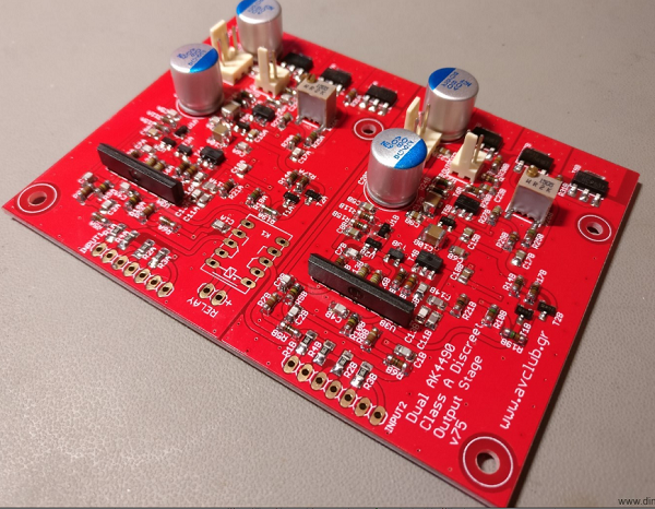
This is the PCB:
And this is the BoM: AK4490 dual mono DAC – Discreet Analog stage BOM (509 downloads)
The BoM includes part numbers for most parts from Mouser. The only parts that are not in production and must be found elsewhere are the UPA68H. Ebay is a good bet. Chances of getting fake parts are pretty small, but just in case do this to double check the ones that you bought: http://www.diyaudio.com/forums/analog-line-level/296406-salas-dcg3-preamp-line-headphone-post5330311.html (Thank you Salas for the info and the idea to use them in the first place!)
The only parts that need matching are T8A with T9A and T8B with T9B. There’s no need to go crazy with the matching – within 5% should be enough.
Power should be ideally +/-16VDC. A bit less is OK (I did my initial testing with +/-12VDC) but more will most likely damage the board. The board is running in class-A so current draw is constant. A power supply with 100mA current capacity should be enough.
Bias current is adjusted by the multi-turn trimmers R26A and R26B. They should be adjusted to their mid value before soldering to the board (~1K). To adjust bias just measure current consumption at one of the rails while turning the pot. Adjust for ~25mA total current draw per rail and per channel. Current draw on the negative rail should be about 1mA higher than on the positive rail. Bias should be re-adjusted if the power supply voltage needs to change.
After bias adjustment and with no input signal you should check for DC at the outputs. If everything went well you should be seeing anywhere between 0 to a few mV of DC voltage.
Read more: Arduino controlled Dual Mono AK4490 DAC (part 3)
- What is the output voltage of this stage?
The stage outputs approximately 2.4V RMS. - Can I find the UPA68H parts on Mouser?
No, these parts are not in production and must be found elsewhere like eBay. - How much do the T8A and T9A transistors need to match?
A matching tolerance within 5% is sufficient. - What is the ideal power supply voltage for this board?
The ideal voltage is +/-16VDC, though +/-12VDC is acceptable. - How much current capacity does the power supply need?
A power supply with 100mA current capacity should be enough. - Where should I adjust the bias current?
Bias current is adjusted by the multi-turn trimmers R26A and R26B. - What is the target current draw per rail?
You should adjust for approximately 25mA total current draw per rail and per channel. - What DC voltage level should I see at the outputs after adjustment?
You should see anywhere between 0 to a few mV of DC voltage.