Remember the old video game Space Invaders? Some of its sound effects were provided by a chip called the 76477 Complex Sound Generation chip. While the sound effects1 produced by this 1978 chip seem primitive today, it was used in many video games, pinball games. But what’s inside this chip and how does it work internally? By reverse-engineering the chip from die photos, we can find out. (Photos courtesy of Sean Riddle.) In this article, I explain how the analog circuits of this chip works and show how the hundreds of transistors on the silicon die form the circuits of this complex chip.
The 76477 chip combines several functional blocks to produce a variety of sound effects. A voltage-controlled oscillator (VCO) produces a signal whose frequency depends on the control voltage. A “super low frequency” SLF oscillator generates a triangle wave. Feeding this into the VCO generates a varying pitch, useful for bird chirps, sirens, or the warbling sound of the UFO in Space Invaders. A “one-shot” produces a pulse of a fixed length to control the length of the sound. An envelope generator makes the sound more realistic by ramping its amplitude (volume) up at the start and down at the end. A digital white noise generator can be used for drums, gunshots, explosions and other similar sound effects. Finally a digital mixer combines these signals and feeds them to the output amplifier.
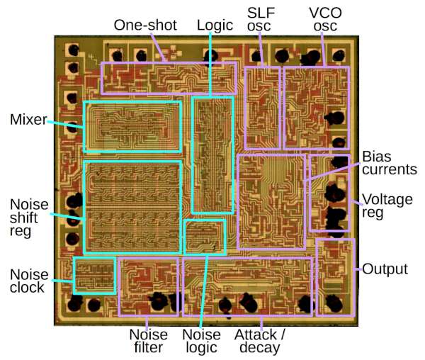
The diagram below indicates the functional blocks on the 76477 die. Looking under a microscope, you can see the circuitry that makes up the chip. The yellowish lines are metal traces that connect the circuits of the die. The reddish and greenish regions are the silicon of the chip, forming transistors and resistors. The black blobs around the edges of the chip show where tiny bond wires connected the die to the integrated circuit pins. Analog circuits are outlined in purple, while digital circuits are in cyan. The 76477 is primarily analog—most control signals are analog, the chip has no digital registers, and most sounds are generated from analog circuits—but about a third of the chip’s area is digital logic.2
The block diagram below shows the chip’s functional elements and can be compared to the die photo above. The chip is primarily controlled by resistors (red pins), capacitors (cyan pins) and voltages (violet pins). This made the chip difficult to control with a microprocessor, and more useful for hardwired sounds.
Read more: Reverse engineering the 76477 sound effect chip