
Summary of Simple Arduino Radio with TEA5767
This Instructable presents a beginner-friendly guide to building an Arduino-based radio using a TEA5767 module and a 2.2" TFT display. The project allows users to manually select from ten pre-defined stations via a single button, avoiding complex frequency scanning. It serves as the first phase of a larger multimedia system intended for future expansion with SD card and Bluetooth capabilities.
Parts used in Simple Arduino Radio:
- Arduino MEGA2560 compatible board
- 2.2" TFT ILI9225 controller
- TEA5767 breakout board
- 1 button
- 1 resistor 10k
- Step up module (3.7V to 5V)
- 3.7V battery (6000mAh)
- Speakers with integrated amplifier
- Wires and breadboard
Ok, before to introduce this project, i want to apologize for my English, my native language is French…
Secondly, this is my first Instructable, and it’s the first part of a biggest project (a MP3/SD card/USB/radio/bluetooth/clock/alarmclock/temperature/humidity on TFT touchscreen 3.5″)
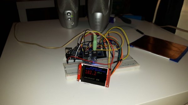
So, I was searching for a tutorial to create a simple Radio with Arduino… And all what I found was very complex sketches for a very simple result, and I didn’t find any tutorials to use it with a TFT and UTFT library.
I decide to create a tutorial for noobs like me which are searching for it.
First , The goods :
– Arduino MEGA2560 compatible (ready for the next steps of the project)
– 2.2″ TFT ILI9225 controller
– TEA5767 breakout board
– 1 button
– 1 resistor 10k
– 1 step up module (from battery 3.7v to 5v)
– 1 battery (here i took a battery from an old tablet 3.7v, 6000mAh)
– Speakers (i used old computer speaker with integrated amplifier for the test)
– Wires and breadboard
– Arduino IDE for the sketch
Step 1: Let’s Go for Wiring
Please be cautious, and wire the battery only when everything is finished !
TFT 2.2″
VCC : +5v
GND : GND
SDI : D51
CLK : D52
CS : D22
RST : D30
RS : D24
TEA5767
VCC : +5v
GND : GND
SCL : 21(SCL)
SDA : 20(SDA)
Button
Resistor 10k on ground
Don’t forget to link the GND wires from TFT and TEA5767 with Arduino GND
Step 2: How Does It Work ?
Remember I said a simple radio !
I should say VERY simple !
I’m using only the same 10 stations, then, I’m not interrested in a radio which scans all the frequencies, is very complicated to use,…
Here, in the sketch you write the different frequencies you want, and the button just changes the stations.
I think I can’t make more simple 🙂
The libraries :
You’ll need 4 libraries :
Wire.h (included in IDE)
TEA5767Radio.h (http://playground.arduino.cc/Main/TEA5767Radio)
EEPROM.h (included in IDE)
UTFT.h (http://www.rinkydinkelectronics.com/library.php?id…
Change the frequencies for the different stations, and the names of the stations.
When your sketch is uploaded, connect the battery by VIN, don’t forget to check output voltage on the stepup module.
To charge the battery, you can use this : http://fr.aliexpress.com/item/Free-Shipping-5V-1A-…
I hope you will enjoy it !
And I’ll make other instructables with the different parts of the projet (waiting for goods)
Read more: Simple Arduino Radio with TEA5767
- What libraries are required for this project?
You need Wire.h, TEA5767Radio.h, EEPROM.h, and UTFT.h. - How do I change the radio stations?
The sketch uses a single button to cycle through ten pre-written frequencies. - When should I connect the battery?
Connect the battery only after all wiring is finished to ensure safety. - Can I use a different microcontroller than the Arduino MEGA2560?
The author specifies using an Arduino MEGA2560 compatible board for this tutorial. - Does the radio scan all available frequencies automatically?
No, it uses only ten fixed stations written directly into the sketch. - How can I charge the 3.7V battery used in this build?
You can charge it using a 5V 1A charger as suggested in the article. - What is the purpose of the step-up module?
It converts the 3.7V battery voltage to 5V for the components.
