
Summary of L293D Motor Controller Tutorial
This article details a DIY project to control four DC motors using two L293D motor driver chips and an Arduino Uno R3. The author overcomes the single-board limitation of one L293D chip by utilizing a second identical chip, connecting them via a mini breadboard with jumper cables. The guide outlines specific wiring connections for power, ground, and signal pins to drive two motors per chip, allowing full control of four motors from a single microcontroller using the Arduino IDE.
Parts used in Four DC Motor Control Project:
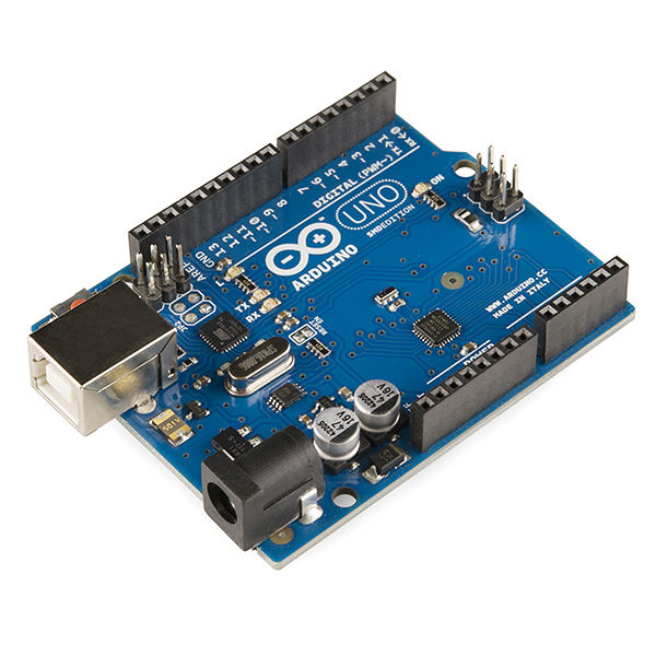
- Arduino Uno R3
- L293D chips (x2)
- BreadBoard (mini)
- BreadBoard pins
- Jumper cables
- DC motors (x4)
L293D is a chip that enable us to control two motors together with only one Arduino board or other microcontrollers. However, I was having a project that required controlling four DC motors together. Recently i brought a L293D Arduino Shields , it covered all of my pins that i need to use them to connect with other breakout board to combine with the motor controller (of course you can buy a L298N motor controller) . I made it, so i decided to share it with u guys now. So let’s get started.
Step 1: Collecting Parts and Programs
In this project, you needed these parts :
1.Aruduino Uno R3 (you can also use the other version of Arduino)
2.L293D chips x2
3.BreadBoard(i am using a breadboard mini)
4.BreadBoard pins(i don’t know whether it’s called Breadboard Pins or not but I am gonna say it that way)
5.Jumper cables
Programs :
You will need Arduino IDE to programs your Arduino ( you can download it from here https://www.arduino.cc/en/Main/Software ) , then download the sketch that i attached and open it up.
Step 2: Connecting the Component
1.Connect the pins with following (did this on both L293D chips):
–Enableand VCC( Vss/Vs in the schematics ) —> 5v pins (connect Vss,Vs,Enable 1,Enable 2 to 5v pins on Arduinno)
-all GND —> GND
2.First L239D (the left one) :
**L293D —> Arduino
–pin 2 (input 1) —> pin 5
–pin3 (output 1) —> pin + on DC motor
–pin 6 (output 2) —> pin – on DC motor
–pin 7 (input 2) —> pin 6
–pin10 (input 3) —> pin 2
–pin 11 (output 3) —> pin – on DC motor
–pin 14 (output 4) —> pin + on DC motor
–pin 15 (input 4) —> pin 1
3.Seconds L239D (the right one) :
**L293D —> Arduino
–pin 2 (input 1) —> pin 7
–pin 3 (output 1) —> pin + on DC motor
Read more: L293D Motor Controller Tutorial
-
How many DC motors can this project control?
The project uses two L293D chips to control four DC motors together. -
What microcontroller is required for this setup?
An Arduino Uno R3 is used, though other versions of Arduino are also acceptable. -
Which software is needed to program the Arduino?
You need the Arduino IDE to program the board and run the attached sketch. -
How should the Enable and VCC pins be connected?
Connect Vss, Vs, Enable 1, and Enable 2 to the 5v pins on the Arduino. -
Where do all GND pins connect?
All GND pins from the L293D chips must be connected to the GND on the Arduino. -
Can I use an L298N motor controller instead?
Yes, the text mentions you can buy an L298N motor controller as an alternative. -
What type of breadboard is recommended?
The author used a mini breadboard, but any suitable breadboard works.
