
Summary of Waterproof 10 Minute Timer
This article details a DIY waterproof 10-minute timer for bathroom use, designed to prevent lateness while allowing users to enjoy hot showers. The project utilizes an Attiny85v microcontroller and three LEDs to display time in binary format, powered by a CR2032 button cell to maximize battery life at low voltages. The author explains component selection, programming via Arduino IDE, and assembly using silicone sealant for water resistance.
Parts used in the Waterproof 10 Minute Timer:
- Three 2.2 kOhm resistors
- Three 3mm LEDs
- Latching push button DPDT switch
- DIP-8 IC socket
- Attiny85v IC
- CR2032 button cell
- CR2032 button cell holder
- Silicone sealant
- Soldering iron/soldering wire
- General purpose circuit board
- Plastic polythene bags
- Plastic cups
Story
I went for a shower one day, was getting late for office. Running tight on time, but I didn’t want to come out of hot shower in cold morning. Without any clock in my bathroom I was saying to myself “Lets enjoy the shower for few more minutes, I might be over estimating the time”. Result: I got really late to my office.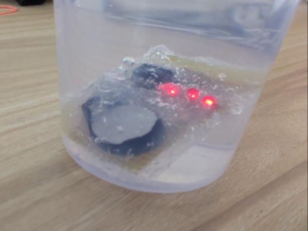
Solution: Put a clock in your bathroom.
Nooooo.
Why would I put a clock in my bathroom when I can make a simple timer on my own. Well this project is just to build a waterproof 10 minute timer so you enjoy your hot bath and reach office on time.
Step 2: Electronics components
We will use three 3mm LEDs to display time in binary i.e. 001 means one minute is past and 111 means 7 minutes are past; here 1 means LED is ON. Now that we are using only 3 LEDs, we can indicate only 8 states using them, so lets agree on lighting up first LED not at the end on 1 minute but after 3 minute and from there every minute we will increment the count. This decision was influenced by the use of small form factor CR2032 button cell as powering source of the circuit, which has capacity of 250mAh only. We will use three 2.2 kOhm resistors for current limiting through LEDs. A latching push button DPDT switch will work as ON/OFF switch. We will use Attiny85v as controller in this circuit as it can support operation up to 1.8v at 1MHz.
Components
- Three 2.2 kOhm resistors
- Three 3mm LEDs
- Latching push button DPDT switch
- DIP-8 IC socket
- Attiny85v IC
- CR2032 button cell
- CR2032 button cell holder
Step 3: Tools
We will use silicone sealant to make our timer water proof. Soldering iron and soldering wire for assembling circuit on general purpose circuit board. Some plastic bags and plastic cups can come handy to take out sealant.
Tool list:
- Silicone sealant,
- Soldering iron/soldering wire,
- General purpose circuit board and
- Some plastic polythene and plastic cups.
Step 4: Why Attiny85v?
To keep size of the timer small, I decided to use a CR2032 button cell. CR2032 is rated at 3v and can go down to 2v when fully discharged. Attiny85 has minimum operating voltage of 2.7v, which will be waste of CR2032’s capacity. On the other hand Attiny85v has minimum operating voltage of 1.8v which is below full discharge voltage of CR2032, resulting in full utilization of button cell. Frequency of operation at lower voltages is going to be low but our application does not demand high frequency operation. Attached image is a snap from Atmel’s datasheet on Attiny microcontrollers.
Step 5: How to program Attiny85v from Arduino IDE?
Arduino IDE does not have support to program Attiny85v by default, you can add Attiny85 (which holds good for Attiny85v) as one of the board in Arduino IDE using THIS LINK.
Once you are done with that set Tools > Programmer to “Arduino as ISP“, select “attiny85” as board and set “Internal 1Mhz” as frequency in Tools menu. After that make connections mentioned in above link and burn the boot loader. As a test you can modify Blinky code for pin number 0 and burn it in Attiny85 to see LED blink at physical pin number 5 of Attiny85v.
Step 6: Schematic
Circuit is quite simple. Attached image’s left half shows a breadboard view of the circuit. Attiny85v is powered by a 3V coin cell CR2032, connected through a switch. Three 3mm LEDs are connected to physical pin 5, 6 and 7 of Attiny85v through a series resistor of 2.2 kOhm. Pins 5,6 and 7 map to GPIO pin 0, 1 and 2 of Arduino. Right half of attached image shows the schematic view of the circuit.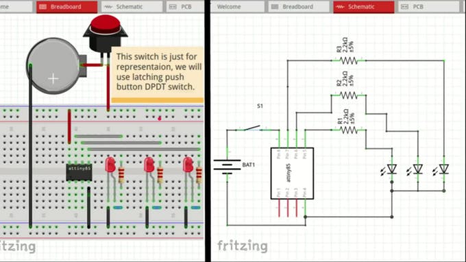
Step 7: Code and assembly on General purpose circuit board
Code is also quite simple. We declare a count variable. Set three pins in output mode, set them low. Put delay of 2 minute in setup function as we plan to count 10 minutes using only 3 LEDs. In loop function we wait for every 1 minute, increment the count and then update the status of LEDs using set_LEDs function. This function uses bit-wise AND to update the status of LEDs.
For more detail: Waterproof 10 Minute Timer
- How does the timer display time?
The timer displays time in binary using three 3mm LEDs where each state represents a specific minute count. - Why was the Attiny85v chosen over the standard Attiny85?
The Attiny85v operates down to 1.8v, allowing full utilization of the CR2032 battery which discharges to 2v, whereas the standard version requires 2.7v. - Can I program the Attiny85v using Arduino IDE?
Yes, but you must first add the Attiny85 board support via a specific link and configure the programmer as Arduino as ISP. - What is the power source capacity of this circuit?
The circuit uses a CR2032 button cell with a capacity of 250mAh. - How are the LEDs connected to the microcontroller?
Three LEDs are connected to physical pins 5, 6, and 7 of the Attiny85v through 2.2 kOhm series resistors. - What tool is used to make the timer waterproof?
Silicone sealant is applied to the assembled circuit to ensure it is waterproof. - Does the timer start counting immediately upon turning on?
No, the code includes a 2-minute delay in the setup function before the counting loop begins. - How many states can the three LEDs indicate?
Using three LEDs allows the circuit to indicate only 8 states.
