
Summary of Traffic Lights Beginner Arduino Project
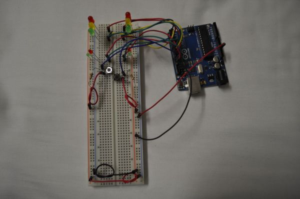
This beginner Arduino project serves as a training tool for learning timer programming and button input handling. It replicates a traffic light system with pedestrian signals using an Arduino Uno, a solder-less breadboard, ten LEDs (various colors and sizes), two 1kΩ resistors, two momentary switches, and jumper wires. The setup involves arranging lights vertically on the breadboard and connecting them to specific digital pins while wiring buttons with pull-down resistors.
Parts used in the Traffic Lights Beginner Arduino Project:
- Arduino
- Solder-less Breadboard
- 10 LEDs (2 Red, 2 Yellow, 2 Green, 2 Small Red, 2 Small Green)
- 2 1Kohm Resistors
- 2 Momentary Switches (normally open)
- Jumper Wires
This is a beginners project for the Arduino. I am using the Arduino Uno but should work with little or no modification on other arduino models.
Setting up the hardware is very easy. This project is more of a training tool for learning how to program a timer list while listening for a button press.
Parts you will need.
– Arduino
– Solder-less Breadboard
– 10 LEDs
— 2 Red
— 2 Yellow
— 2 Green
— 2 Small Red
— 2 Small Green
– 2 1Kohm Resistors
– 2 Momentary Switches (normally open)
– Jumper Wires
Step 1: The Circuit

Step 2: Setup LEDs
Setup the lights on the breadboard like a traffic light. Red on top, then yellow, and then green. The small red and green are the pedestrian crossing signals. Again red on top and green just below.
In my images I am using the right side positive run of the breadboard as negative because its easier to put in the LED.
Put the cathode (-) into the negative run of the breadboard and the anode (+) into a hole next to it.
Step 3: Buttons
Put the buttons in so you have at least 2 pin holes space to add the wires and resistors. Place the 1kohm resistor between one side of the button and the negative run on the breadboard.
Step 4: Wire up LEDs
There are a lot of wire in this project so try to keep it neat so you know where everything is going.
Start by linking the two power rails of the breadboard and giving the breadboard power from the arduino.
An easy way to wire the lights is to just start from the top and work your way down.
Wire guide:
LED / Pin
Side A
Red = 4
Yellow = 3
Green = 2
Small Red = 7
Small Green = 6
Side B
Red = 10
Yellow = 9
Green = 8
Small Red = 13
Small Green = 12
– Solder-less Breadboard
– 10 LEDs
For more detail: Traffic Lights Beginner Arduino Project
-
What is the primary purpose of this Arduino project?
This project acts as a training tool for learning how to program a timer list while listening for a button press. -
Can this project work with Arduino models other than the Uno?
Yes, it should work with little or no modification on other Arduino models. -
How should the main traffic lights be arranged on the breadboard?
The lights should be set up like a traffic light with red on top, then yellow, and then green. -
Which pins are used for the small red and green pedestrian signals on Side A?
The small red signal uses pin 7 and the small green signal uses pin 6. -
How should the 1kohm resistor be connected to the buttons?
Place the 1kohm resistor between one side of the button and the negative run on the breadboard. -
What is the recommended method for wiring the LEDs on the breadboard?
Start from the top and work your way down to keep the many wires neat and organized. -
Where should the cathode (-) of the LED be inserted?
The cathode should be put into the negative run of the breadboard.
