
Summary of Big Ball Maze Game using Arduino
This oversized 48” tilt-maze lets players guide balls to the center by tilting a circular board via gearmotors controlled by an Arduino. Control options include a wired accelerometer handheld, an Android phone over Bluetooth, or body movement using sonar sensors. The board has acrylic maze walls set into routed slots; tilt feedback uses an onboard accelerometer. Two motors pull strings to tilt front/back and left/right. Full build files and parts list were provided for fabrication and assembly.
Parts used in the Big Ball Maze:
- Arduino microcontroller – Uno or compatible (Sparkfun DEV-11021)
- Arduino prototyping shield – Adafruit #51
- Bluetooth module – Bluetooth Mate Gold (Sparkfun WRL-09358)
- Accelerometer modules (2) – 2 axis or 3 axis (Sparkfun SEN-00849 and Modern Device MD0500)
- Ultrasonic rangefinders (2) – Maxbotix XL-Maxsonar EZ0 (Sparkfun SEN-09491)
- Motor drivers (2) - Dual VNH2SP30 (Pololu #708)
- Battery – 12V 10Ah SLA (Universal S3BATT)
- Battery charger – 12V 4A 3 stage (Energizer 84028)
- RJ11 cables (3) – 6 conductor, 6 foot long (Startech RJ6FT)
- RJ11 jacks (6) – 6 conductor (6P6C) (Jameco #124039)
- DC power cable – 16AWG speaker wire, 3’ total
- Resistor – 560 ohm 1/4 watt
- LED
- Stripboard – prototyping circuit board
- Jumper wire – 22AWG multiple colors
- Switch – momentary SPST
- Switch – DPDT pushbutton ON-OFF
- Gear motors (2) – 12V, 19:1, 500 rpm, 5 kg-cm torque (Pololu #1102)
- Gears 60 tooth (2) - 32 pitch acetal hub gears (ServoCity #RHA32-36-60)
- Gears 30 tooth (2) - 32 pitch acetal hub gears (ServoCity #RHA32-36-30)
- Set screw hubs (2) – 6mm bore (ServoCity #3472H)
- Set screw hubs (2) – 5/16” bore (ServoCity #3466H)
- Hex key – 3/32” (ServoCity #7122A16)
- Hub screws (16) - #5-40 3/8” panhead (ServoCity #90272A126)
- Screws – motors (12) – M3 x 10mm panhead (ServoCity #92005A120)
- Screws (8) – flat head ½” long brass wood screws
- Shafts (2) – 5/16” x 90mm
- Bearings (4) – 5/16” ID skateboard bearings
- Non-slip tape – 300mm length
- Plywood – 3/4” x 1220mm x 1220mm (for board and stand)
- Acrylic strips (7) – 1220mm x 1 3/4” clear
- Acrylic strips (3) – 1220mm x 2 1/4” clear
- Screws (30) – small 1/2” long panhead with washers
- Screw rings (4)
- MDF – 1/4” x 610mm x 410mm
- Shafts (4) – 5/16” x 108mm
- Pulleys (4) – 5/16” shaft, 1 15/16” OD (McMaster-Carr #3434T39)
- Bushings (8) – 5/16” ID x 38mm aluminium tube
- Threaded rod (4) – 5/16”-18 x 150mm
- Lock nuts (8) – 5/16”-18
- Washers (8) – 5/16”
- Cord – 3mm, 3700mm total
- Wire hooks (4)
- PVC pipe – 1 1/4” x 10”
- PVC coupling – 1 1/2”
- PVC coupling – 2”
- Screws (4) - #10-32 x 3/4” flathead
- Lock nuts (4) - #10-32
- Screws (2) - #10 x 3/4” flathead wood screws
- Balls – 57mm diameter Bocce Pallinos (Epco)
This project was the result of an urge to contribute something to the Creative Games section of my kids’ elementary school fair. The kids loved it for it’s simple old-school game aesthetic mixed with Wii-style and Kinect-style video game control. It’s a spin-off project of an earlier Ball & Plate experiment mentioned here in the Instructables forums.

The machine is an over-sized (1200mm (48”) diameter) version of the traditionally hand-held game where the object is to tilt a circular disc to move one or more balls though to the center of a maze. The circular board is supported by a stand with a centrally mounted gimbal, and controlled by either a wired hand-held contoller, an Android phone, or by body movements.
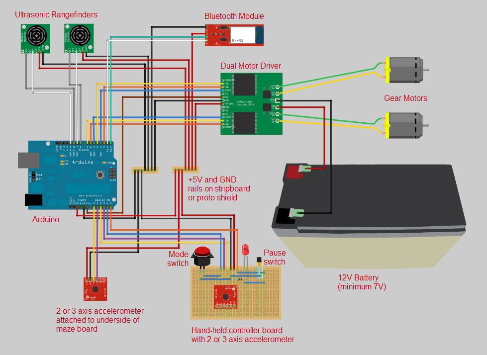
An Arduino microcontroller is used to monitor the player’s actions and then adjust the tilt of the board to match. The wired controller uses an accelerometer module. The Android phone controller uses the in-built accelerometer and a custom app made with Processing to communicate via bluetooth with the Arduino. The body controller uses two sonar proximity sensors to detect how far the operator is from a central position to determine how much to tilt the board.
The board is tilted using two gearmotors pulling on strings attached to the underside of the board – one for front and back, and one for left and right. An accelerometer is attached to the underside of the board to provide the position feedback to the Arduino.
Step 1: The board
The outer maze wall is 57.15mm (2¼”) wide strips of 3.175mm (1/8”) thick clear acrylic. These are screwed at regular intervals around the edge of the board with wood screws and washers, and positioned so that the lower edge is flush with the underside of the board. The inner maze walls are 44.45mm (1¾”) wide strips of the same acrylic, so that once they are bedded into the 6.35mm (¼”) deep slots, they are the same height as the outer wall.
The inner two rings of walls have to be softened in an oven before they can be bent enough to fit the tighter radii of the slots. This can be a tricky operation. I placed the acrylic strips (one at a time) on a baking sheet and kept the oven at a low temperature and continually checked so that the acrylic didn’t get too soft. Make sure you’re wearing gloves when you get the acrylic out of the oven.
The walls need to be glued into their slots. Even if they are a snug fit, the banging of the ball eventually pops them out.
 disk.eps5 MBdisk.crv695 KB
Step 2: The stand
Cut the main leg pieces out of a 1200mm x 1200mm (48” x 48”) sheet of 19mm (¾”) plywood using the attached design (legs.eps). If you have access to a CNC router, I’ve also attached the Vcarve file (legs.crv). Cut the rectangular pieces out of 6.35mm (¼”) MDF using the attached design (quarterInchBoard.eps, quarterInchBoard.crv).
Assemble each of the four pulley shafts by sliding the pulley onto the (108mm) 4¼” x (7.94mm) 5/16” shaft, and then the 38mm (1½”) long tubing onto each side of the pulley. Add a drop of light oil so the pulley spins nicely.
Assemble the parts according to the pictures.
legs.eps5 MBquarterInchBoard.crv503 KBlegs.crv3 MBBigBallMaze.123d2 MBMaterials
Arduino microcontroller – Uno or compatible (Sparkfun DEV-11021)
Arduino prototyping shield – (Adafruit #51)
Bluetooth module – Bluetooth Mate Gold (Sparkfun WRL-09358)
Accelerometer modules (2) – 2 axis (or 3 axis) (Sparkfun SEN-00849 and Modern Device MD0500)
Ultrasonic Rangefinders (2) – Maxbotix XL-Maxsonar EZ0 (Sparkfun SEN-09491)
Motor drivers (2) – Dual VNH2SP30 (Pololu #708)
Battery – 12V 10Ah SLA (Universal S3BATT)
Battery charger – 12V 4A 3 stage (Energizer 84028)
RJ11 cables (3) – 6 conductor, 6 foot long (Startech RJ6FT)
RJ11 jacks (6) – 6 conductor (6P6C) (Jameco #124039)
DC power cable – 16AWG speaker wire, 3’ total
Resistor – 560ohm 1/4watt
LED – any old LED
Stripboard – prototyping circuit board
Jumper wire – 22AWG multiple colors
Switch – momentary SPST
Switch – DPDT pushbutton ON-OFF
Motor Housings
Gear motors (2) – 12volt, 19:1gear ratio, 500rpm, 5kg-cm (84oz-in) torque (Pololu #1102)
Gears 60 tooth (2) – 32 pitch acetal hub gears (ServoCity #RHA32-36-60)
Gears 30 tooth (2) – 32 pitch acetal hub gears (ServoCity #RHA32-36-30)
Set Screw Hubs (2) – 6mm bore (ServoCity #3472H)
Set Screw Hubs (2) – 5/16” bore (ServoCity #3466H)
Hex key – 3/32” (ServoCity #7122A16)
Hub screws (16) – #5-40 3/8” panhead (ServoCity #90272A126)
Screws – motors (12) – M3 x 10mm panhead (ServoCity #92005A120)
Screws (8) – flat head ½”long brass wood screws
Shafts (2) – 5/16” x 90mm
Bearings (4) – 5/16” ID skateboard bearings
Non-slip tape – 300mm length
The Board
Plywood – ¾” x 1220mm (48”) x 1220mm (48”)
Acrylic strips (7) – 1220mm (48”) x 1¾” clear
Acrylic strips (3) – 1220mm (48”) x 2¼” clear
Screws (30) – small ½” long panhead with washers
Screw rings (4)
The Stand
Plywood – ¾” x 1220mm (48”) x 1220mm (48”)
MDF – ¼” x 610mm (24”) x 410mm (16”)
Shafts (4) – 5/16” x 108mm
Pulleys (4) – 5/16” shaft, 1 15/16” OD (McMaster-Carr #3434T39)
Bushings (8) – 5/16” ID x 38mm (1½”) Aluminium tube
Threaded rod (4) – 5/16”-18 x 150mm (6”)
Lock nuts (8) – 5/16”-18
Washers (8) – 5/16”
Cord – 3mm (1/8”) cord, 3700mm (12’)
Wire hooks (4) – to attach to the ends of the cord
The Shaft and Gimbal
PVC pipe – 1¼” x 10”
PVC coupling – 1½”
PVC coupling – 2”
Screws (4) – #10-32 x ¾” flathead
Lock nuts (4) – #10-32
Screws (2) – #10 x ¾” flathead wood screws
The Balls
Balls – 57mm diam Bocce Pallinos (Epco)
- What size is the circular board?
The board is 1200mm (48”) diameter made from 19mm (3/4”) plywood. - How is the board tilted?
Two gearmotors pull strings attached under the board, one for front/back and one for left/right. - What controllers can be used to play?
Controls include a wired handheld accelerometer controller, an Android phone app via Bluetooth, or body movement using two sonar sensors. - What provides tilt feedback to the Arduino?
An accelerometer attached to the underside of the board provides position feedback. - What materials are used for the maze walls?
Clear acrylic strips in 1 3/4” and 2 1/4” widths are bedded into 1/8” wide, 1/4” deep slots in the plywood board. - How are the tighter radius acrylic walls bent?
Inner rings are softened in a low-temperature oven and carefully bent while wearing gloves. - Which microcontroller runs the game?
An Arduino Uno or compatible runs the sensors and motor control. - What motors and gear ratios are used?
12V gear motors, 19:1 ratio, 500 rpm, about 5 kg-cm torque (Pololu #1102) are used. - How are the acrylic walls secured?
They are screwed around the board edge with wood screws and washers and glued into their slots to prevent popping out. - What files are provided for fabrication?
Design files include disk.eps, disk.crv, legs.eps, legs.crv, quarterInchBoard.eps, quarterInchBoard.crv, and BigBallMaze.123d.