Summary of Arduino powered 7seg led display with Port Manipulation
This article introduces Direct Port Manipulation on Arduino to control a 2-digit common anode 7-segment display more efficiently than standard digitalWrite commands. By manipulating entire port banks (B and D) simultaneously, users can update all segments at once, simplifying code for counting or potentiometer-controlled displays. The project highlights the speed benefits and reduced complexity of direct hardware access over abstracted functions.
Parts used in the Arduino 7-Segment Display Project:
- Arduino Uno
- 2 digit 7 segmented display (common anode)
- 14 660ohm resistors
- Breadboard
- Wire
- USB cable
- Potentiometer (optional)
Time for something a little more advanced. Direct Port Manipulation. Normally when using Arduino software, the actual logic behind changing the values in pins is abstracted away with digitalRead and digitalWrite. Now, for most people that’s just fine. But it has some limitations. For one, it is a little slower than might be practical for some situations and it can only change one pin at a time. But what if you wanted to change ALL the pins at the same time? Annoying with digitalWrite, but super easy with Port Manipulation.
What we’re using today to demonstrate this is a 7 segmented display. There are seven separate segments, each with a single LED that is individually operated. When combinations are set, you get a number. Using digitalWrite, you would have to write out that command seven times for just one number and there are ten possible numbers for each digit! You can see how this can get really complicated for doing something as simple as counting up.
It’s easy to setup, but takes some planning in the code.
Just another one of the many things that I made at TechShop today.
Step 1: Materials
Arduino Uno
2 digit 7 segmented display (common anode)
14 660ohm resistors
breadboard
wire
usb cable
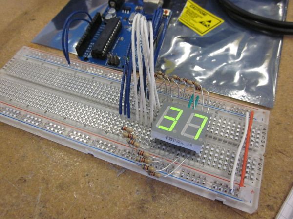
Step 2: Circuit
This is the way a 2 digit common anode display would be attached. Common anode means that all the led’s share a common power supply. So in order so turn one on, the pin will be set to LOW.
KEEP TRACK OF WHAT WIRES GO TO WHAT LED! You’re going to use that information to build the port mapping later.
A potentiometer is added just in case you want to get fancy and have the pot control the number instead of just counting up. This is not too much more difficult, so go ahead and try it.

Step 3: Port Manipulation Mapping
This is the pin mapping for the arduino uno. Notice that each port there is a designation right next to the pin that looks like “PX#”. This is the pin number for that letter bank. There are multiple banks in this chip. The ones we care about are bank B and D. They are the ones to be manipulated. Write down the pin and corresponding port bank id for all the leds. The next part will be to combine them.
2 digit 7 segmented display
For more detail: Arduino powered 7seg led display with Port Manipulation
- Why use Direct Port Manipulation instead of digitalWrite?
It is faster and allows changing all pins at the same time. - What type of 7-segment display is used in this project?
A 2-digit common anode display is used where LEDs share a common power supply. - How do you turn on an LED in a common anode display?
You set the pin to LOW to turn one on. - Which port banks are manipulated for the Arduino Uno?
The project manipulates bank B and bank D. - What is the purpose of adding a potentiometer?
The potentiometer can be used to control the number displayed instead of just counting up. - Why is digitalRead and digitalWrite considered limited here?
They are slower and can only change one pin at a time. - How many resistors are required for the circuit?
14 resistors with a value of 660 ohms are needed. - What information must be kept track of during wiring?
You must keep track of what wires go to what LED to build the port mapping later.