Interfacing a RC radio to a microcontroller is a bit of a pain, especially if you want a lot of channels, because you have to time each channel’s output individually.
An AVR only has one 16 bit timer with two compare channels, so either you can only use two channels at full resolution or you have to waste lots of cycles sampling it.
The other hassle is having loads of wires running from the rx to the micro.
The receiver on the FlySky 9x uses SPI to send data from the radio chip to the chip that actually generates the timings on each output channel.
If we tap off the SPI lines we can listen directly to the serial data the radio is spewing out… Luckily its super easy to understand!
Step 1: Cables
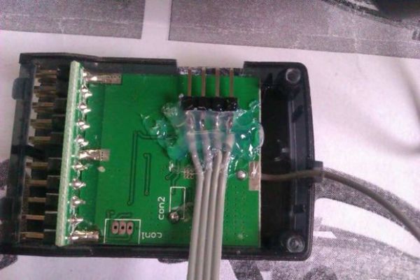
Break off 4 pins of SIL 0.1″ header. Plug in some jumper leads to get the sizing, then solder on some ribbon cable. About 15cm will do the trick.
I’d recommend 80 way ATA hard drive cable (the thin stuff, not like this)
Step 2: Cutting
Cut out a hole in the side of the box, and glue the header down so the pins are flush with the outside of the case
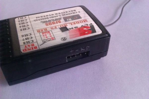
Step 3: Power
Solder the power leads to the conveniently provided pads. The other side isn’t quite so easy…
The edge one is +ve, the middle is -ve.
Step 4: Data
Get some very thin wire (speaker wire or 80 way HDD cable)
We’re soldering onto the MOSI and SCK pins shown in the picture.
For more detail: SPI interface to the FlySky/Turnigy 9x