Summary of Arduino Based Lie Detector
Summary: This tutorial describes building an Arduino-based lie detector that gives visual feedback via three LEDs (red, green, blue) and an audible buzzer. A touch plate sensor on an analog input measures galvanic skin response (GSR); readings compared to a potentiometer-adjustable threshold determine LED color and buzzer activation. The final circuit can be made standalone without the Arduino programmer.
Parts used in the Arduino Based Lie Detector:
- Arduino Duemilanove or Arduino Uno
- Touch plate (GSR sensor)
- Three LEDs (red, green, blue)
- Resistors for LEDs
- Buzzer
- Potentiometer
- Wiring/jumper wires
- Power supply for standalone operation
- Breadboard or PCB for final assembly
We have previously posted the the project lie detector, now here is is also a lie detector using arduino. Here is a simple tutorial to build a simple lie detector which will give visual indication through LED arrangement whether the person speaks lie or truth. The project uses a arduino duemilanove or uno. So the project is based on arduino.
But our final circuit will be standalone circuit without attached arduino programmer.
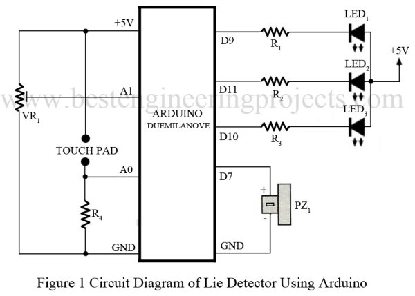
Circuit Description:
Wiring diagram is very simple, we simply connected three LED to 3 different digital pins as
shown in diagram. A touch Plate is connected to an analog pin.
Software:
Her is a simple version of software:
int redPin = 9;
int greenPin = 10;
int bluePin = 11;
int buzzerPin = 7;
int potPin = 1;
int sensorPin = 0;
long red = 0xFF0000;
long green = 0x00FF00;
long blue = 0x000080;
int band = 10;
// adjust for sensitivity
void setup()
{
pinMode(potPin, INPUT);
pinMode(sensorPin, INPUT);
pinMode(redPin, OUTPUT);
pinMode(greenPin, OUTPUT);
pinMode(bluePin, OUTPUT);
pinMode(buzzerPin, OUTPUT);
}
void loop()
{
int gsr = analogRead(sensorPin);
int pot = analogRead(potPin);
if (gsr > pot + band)
{
setColor(red);
beep();
}
else if (gsr < pot – band)
{
setColor(blue);
}
else
{
setColor(green);
}
}
void setColor(long rgb)
{
int red = rgb >> 16;
int green = (rgb >> 8) & 0xFF;
int blue = rgb & 0xFF;
analogWrite(redPin, 255 – red);
analogWrite(greenPin, 255 – green);
analogWrite(bluePin, 255 – blue);
}
void beep()
{
// 5 Khz for 1/5th second
for (int i = 0; i < 1000; i++)
{
digitalWrite(buzzerPin, HIGH);
delayMicroseconds(100);
digitalWrite(buzzerPin, LOW);
delayMicroseconds(100);
}
}
For more detail: Arduino Based Lie Detector
- What does the project use to detect lies?
The project uses a touch plate measuring galvanic skin response on an analog pin compared to a potentiometer threshold. - Can the circuit be made standalone without the Arduino programmer?
Yes, the article states the final circuit will be standalone without the attached Arduino programmer. - How is visual feedback provided?
Visual indication is provided by three LEDs connected to three different digital pins for red, green, and blue. - Which Arduino boards are mentioned for the project?
The Arduino Duemilanove and Arduino Uno are mentioned. - How is sensitivity adjusted?
Sensitivity is adjusted with a potentiometer read on an analog pin and a band variable in the code. - What happens when the sensor reading exceeds the threshold plus band?
The code sets the LED color to red and triggers the beep function to sound the buzzer. - What color indicates a truth or neutral reading?
The code sets the LED color to green for readings within the threshold band, indicating neutral/truth region. - Which pin is used for the buzzer in the provided code?
The buzzer is connected to digital pin 7 in the code. - How does the setColor function control LED brightness?
setColor extracts RGB components from a long value and uses analogWrite on the red, green, and blue pins, inverting values with 255 minus component. - What frequency and duration does beep produce?
beep toggles the buzzer pin to produce a roughly 5 kHz tone for about one fifth of a second as implemented in the loop.