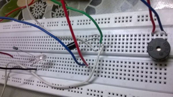
In this tutorial i will show you , how to make a simple Inexpensive Intrusion Detection(Burglar alarm) using an Arduino Uno board . This project uses the Infrared Emitter-Detector pair to detect intrusion and triggers an alarm as soon as the object crosses the infrared field .
** To see a Similar Project Made with an LDR click here
**To see more simple arduino projects check out my blog
http://learnthroughexample.blogspot.in/search/label/arduino
Step 1: REQUIREMENT :
- Arduino uno R3
- Breadboard
- Connecting wires / Jumper cables
- Infrared Emitter and Detector pair LED(not the sensor module)
- PCB mount BUZZER
- 1kohm Resistor
- 10kohm PotentiometeR
** the white LED is the Infrared emitter ,While the black is the Infrared Detector .
 Step 2: CIRCUIT DIAGRAM :
Step 3: SOURCE CODE:
int dtect=8;
int sense=A0;
int buzzpin=9;
void setup()
{
  pinMode(dtect,OUTPUT);
  pinMode(sense,INPUT);
  pinMode(buzzpin,OUTPUT);
  digitalWrite(dtect,HIGH);
  Serial.begin(9600);
}
void loop()
{
int val=analogRead(sense);
Serial.println(val);
if(val>=1005)
{
buzz(50);
}
}void buzz(unsigned char time)
{
analogWrite(buzzpin,170);
delay(time);
analogWrite(buzzpin,0);
delay(time);
}Step 4: DISCUSSIONS :
First build the circuit according to the circuit diagram provided .
Now i will explain to you how the circuit works .
- The white Led you see in the pictures is an Infrared Emitter . You power it on like a normal LED .
- Now if this is your first time with an IR Led , its very common that you’ll mistake your LED to be spoiled as you wont find it glowing ,but that isn’t the case really .
- Infrared light is out of the visible spectrum range so even if it is glowing , you wont be able to see it with naked eyes.
- To see if your emitter LED(White) is working properly : switch on your cell phone camera and see the LED through it , you will see that there is a purple Glow .
- This ensures that your IR emitter (White ) is working perfectly and it is emitting light of a particular range of frequency . Now lets come to the Black LED .
- The back LED is the IR detector. The reason that it is made black is that Black color has the highest absorption ; so it Absorbs most of the infrared light Emitted by the Emitter .
- Now what happens if an object stands in between the Emitter and the detector ?? . OBVIOUSLY the amount of infrared radiations intercepted by the detector will now be lesser due to the obstruction .This is the catch !! .
- When such a situation occurs , I trigger the alarm to denote Intrusion .
 Now that you’ve got your concept right , LETS FOCUS ON THE CODE .
- In line 10 we begin the serial communication to see the values being intercepted on the serial monitor for both the cases i.e
- case 1.) no obstruction in the path of the emitter and the detector .
- case 2.)obstruction in the path of the emitter and the detector .
- for both these cases , we have to observe the values being reflected on the serial monitor , based on which we will decide for which value being exceeded we will be triggering the alarm .
- Note that for my experiment the threshold value was set to 1005 . This might not be the case for you. Hence try to monitor the values that you are intercepting and choose your threshold accordingly .
**Well , hope I have covered all the concepts in detail regarding this project . If you face problems or if you need further detailing on any sub-topic , then please do leave me a comment .
For more detail: ARDUINO Burglar Alarm Using Infrared Emitter-Detector pair

