
Summary of Reading pulses from meters with pulse outputs.. using arduino
This document explains methods for counting pulses from utility meters (up to 12) using continuous sampling and direct port manipulation on Arduino instead of interrupts. It covers interrupt-based counting for one or two meters, optical (LED) sensing, wired/switched S0 outputs, pulse characteristics (pulse width, energy per pulse, power calculation), interfacing tips, pull-up/pull-down recommendations, isolation and safety concerns, and suggested sensor/circuit components and mitigations for noise.
Parts used in the Pulse Counting Project:
- Arduino (or emonTx/emonPi)
- Optical pulse sensor with RJ45 plug (photo-diode plus two-transistor amplifier-driver PCB)
- Photo-diode or photo-transistor
- Light-dependent resistor (not recommended)
- Pull-up resistor (1 kΩ recommended if needed)
- Small capacitor (e.g., 100 nF) for noise suppression
- Wired/switched pulse output connection (S0 interface)
- Isolation circuit (for mains-linked pulse outputs)
- 3.3V or 5V supply for pull-up/operating voltage
A note on what this document covers
The key addition to the wealth of online information about pulse counting is the method of counting pulses from multiple sources (up to 12) using continuous sampling and direct port manipulation in an Arduino sketch instead of interrupt-based counting.
When tallying pulses from one or two pulse output meters, it is recommended to utilize the interrupt approach. The Arduino has just two interrupt pins, but if you need to monitor pulses from additional sources, continue reading!
There is information available on connecting with wired or switched pulse outputs as well.
Introduction
Several meters come with pulse outputs, such as electrical meters like single-phase, three-phase, import, and export meters. Gas meters, water meters, and so on.
The pulsating output could either be a blinking LED or a switching relay, which is typically solid state, or possibly both.
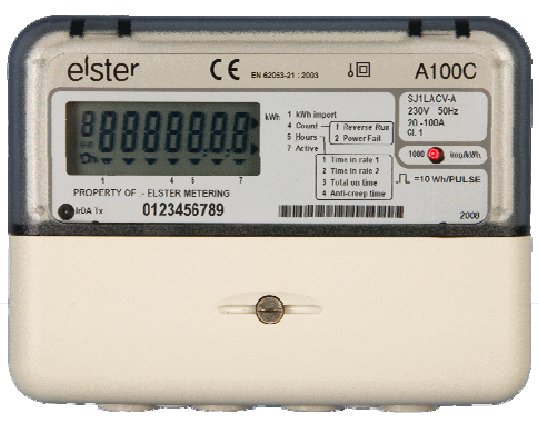
For an electricity meter, each pulse output represents a specific quantity of energy flowing through the meter (measured in Kwhr/Wh). For household single-phase electricity meters (e.g., Each pulse in Elster A100c) usually represents 1 Wh (1000 pulses per kwh). In the situation of higher power meters, such as three-phase ones, each pulse represents a larger energy value. 2 watt-hours per pulse or possibly even 10 watt-hours per pulse.
Figure 1 represents a pulse output. The duration of the high pulse, T_high, changes based on the pulse output gauge. Certain pulse output meters have the capability to adjust the value of T_high. The temperature remains consistent throughout the operation. T_high for the A100c pulse output meter is set at 50 milliseconds. The power measured by the meter is indicated by the duration of T_low between the pulses.
 Calculating Energy
For the A100c meter each pulse represents a 1000th of a KWhr of 1Whr of energy passing through the meter.
Calculating Power
3600 seconds per hour = 3600J per pulse ie. 1 Whr= 3600J
therefore instantaneous power P=3600/T where T is the time between the falling edge of each pulse.
Optical Pulse Counting: Flashing LEDs
A lot of electricity meters either lack pulse output connections or have connections that are not easily accessible because of utility company restrictions. Every contemporary meter contains a light-emitting diode optical pulse output. An optical sensor can be utilized to connect with the meter in those situations.
The A100c picture above shows the red pulse-output LED. In order to identify the pulses emitted by the LED, a light sensor is required, which can be found on the [link to shop page]. This comes with a RJ45 plug for conveniently connecting to the pulse input of an emonTx or emonPi.
A photo-diode and a two-transistor amplifier-driver circuit are housed within the sensor’s small p.c.b.
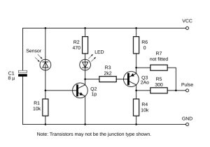
The circuit functions effectively overall, but it does have some drawbacks: it is sensitive to surrounding light, requiring protection from strong light; the green LED may not accurately indicate the output status, resulting in a logic high output without the green LED illuminating.
The pulse input of the emonTx and emonPi comes with the internal pull-up active to avoid counting spurious pulses when nothing is connected, although the resistor R4 has the ability to pull the output down when the transistor is turned off. Adding a pull-up resistor or an external pull-down should not be needed. In case of intense interference, a relatively small capacitor can be added between the pulse output and GND. The pulse width and maximum pulse rate will determine its value, starting with 100 nF would be advisable.
Other Optical Sensors
Other sensors that operate in the visible and infra-red ranges should be usable. A photo-diode or photo-transistor will be suitable, and you will need a similar interface circuit to give a usable pulse output. A light-dependent resistor is unlikely to be satisfactory due to its very slow response time.
Wired / Switched Output Pulse Detection
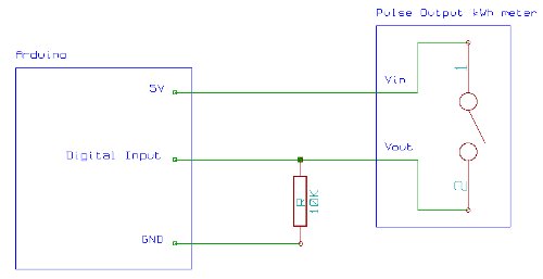
A wired pulse output is present in a lot of meters. Frequently, this will be identified or explained in the documentation as “S0”. The S0 interface, as defined in EN62053-31, is a standardized hardware interface. In the meter, there is a switch – possibly a reed relay but probably an optically isolated transistor. The emonTx or emonPi must provide the required operating voltage.
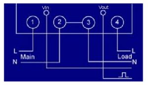
The “S0-” terminal of the meter needs to be connected to GND, while the “S0+” terminal should be connected to the pulse input. If the internal pull-up is not powerful enough, a 1 kΩ resistor should be linked between the 3.3 V terminal and the pulse input for ample current flow.
If the meter’s pulse output does not have the “S0” label, then you must understand that it is not suitable for direct connection with an Arduino, emonTx, or emonPi and figure out its specific functionality. A connection at high voltage may be necessary, and isolation will need to be implemented.
Wired / Switched Output Supply Voltage
From what I understand, 24V is a fairly standard supply for such meter systems, but other voltages can usually be used. Meters often have a fairly wide pulse output supply voltage range of 3 to 35V. So the 5V supply from an Arduino could be used. Higher voltages are desirable when there is more noise in the environment and the cable runs are longer.
Safety
Be cautious of pulse outputs connected to the mains: Ensure that the pulse output of your meter is not linked to the high voltage mains inside the meter. Certain meters have a pulse output connector linked to the neutral. If your meter falls into this category, you will require an isolation circuit to connect it to an Arduino.
Live wire proximity: The pulse outputs are usually very close to live wires, so watch out for those too!
Further Reading
- http://www.arduino.cc/cgi-bin/yabb2/YaBB.pl?num=1276096046
- Single optical pulse counting using a JeeNode board and a Hope RFM12 RF module
- Application instructions energy meter Topic: S0-pulse interface
Source: Reading pulses from meters with pulse outputs..
- Can I count pulses from more than two meters with an Arduino?
Yes; the document describes using continuous sampling and direct port manipulation to count pulses from up to 12 sources instead of relying on interrupts. - When should I use interrupts for pulse counting?
The interrupt approach is recommended when tallying pulses from one or two pulse output meters. - What does each pulse from an A100c meter represent?
Each pulse for the A100c single-phase meter represents 1 Wh, or 1/1000 of a kWh. - How can I calculate instantaneous power from pulse timing?
Instantaneous power P can be calculated as 3600 divided by T, where T is the time in seconds between the falling edges of pulses. - What optical sensor components are suitable for reading meter LEDs?
A photo-diode or photo-transistor with an amplifier/driver circuit is suitable; a light-dependent resistor is unlikely to be satisfactory due to slow response. - Do I need an external pull-up resistor for S0 wired outputs?
If the internal pull-up is not strong enough, a 1 kΩ resistor between 3.3 V and the pulse input is recommended for adequate current. - Should I add a capacitor on the pulse input?
In case of intense interference, a small capacitor (starting at 100 nF) between the pulse output and GND can help, but its value depends on pulse width and maximum pulse rate. - What supply voltages are typical for wired pulse outputs?
Pulse output supply voltages commonly range from 3 to 35 V, with 24 V being fairly standard; 5 V from an Arduino can often be used. - When is isolation required for connecting a meter pulse output?
Isolation is required if the meter pulse output is linked to mains or neutral or if the output is not suitable for direct connection to Arduino/emonTx/emonPi. - What safety cautions are mentioned for pulse connections?
Ensure the pulse output is not connected to high voltage mains, beware of outputs linked to neutral, and watch for live wire proximity; use isolation when necessary.
