Summary of Time Lapse Digital Camera using Arduino
This project converts a standard digital camera into an automated time-lapse device using an Arduino, a relay, and makeAVI software. The modification involves disassembling the camera to access shutter terminals, soldering wires to them, and connecting these wires to a normally open relay. An Arduino controls the relay via a 5V signal on pin 7, effectively simulating a button press to capture images at set intervals.
Parts used in the Time Lapse Digital Camera:
- Digital camera
- Arduino
- Normally open relay
- Soldering wire
- makeAVI software
Following the instructable here, I was able to turn an old digital camera into a time lapse camera using an arduino, a relay, and an open source software program called makeAVI (windows). To modify the camera I disassembled the camera cover and removed the button that activates the shutter.
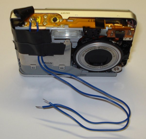
It is difficult to tell from the picture, but pressing the shutter button pushes two copper terminals together sending a signal to the camera to take the picture. I soldered a wire to each of the copper terminals. Touching the free ends of each of these wires together is equivalent to pushing the shutter button to take a picture. The next step was to use a normally open relay (sourced from RadioShack) to control when the shutter was activated.
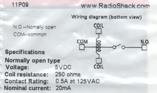
The wiring diagram included with the relay distills the operation of the relay quite nicely. In laymen terms, proving a 5V signal to the coil closes the switch. If a wire from the shutter is connected to the “COM” and “N.O.” pins on the relay then activating the relay takes a picture. In the picture above the yellow wire is connected from arduino pin 7 to a coil pin on the relay. The green wire connects the other relay coil pin to ground. When the arduino makes pin 7 HIGH, the relay closes and tells the camera to take a picture.
For more detail: Time Lapse Digital Camera using Arduino
- How do I modify the camera to take pictures automatically?
Disassemble the camera cover, remove the shutter button, and solder wires to the two copper terminals that activate the shutter. - Can I use makeAVI for this project?
Yes, makeAVI is the open source software program used for Windows to manage the time lapse process. - What type of relay is required for the wiring?
A normally open relay sourced from RadioShack is used to control when the shutter is activated. - Does the Arduino need to send a specific voltage to trigger the camera?
Yes, providing a 5V signal to the relay coil closes the switch and takes a picture. - Which Arduino pin should be used to control the relay?
Arduino pin 7 is connected to the relay coil to activate the shutter. - How does the relay simulate pressing the shutter button?
Connecting a wire from the shutter to the COM and N.O pins allows the relay to close the circuit equivalent to pushing the button. - What happens when the Arduino makes pin 7 HIGH?
The relay closes and tells the camera to take a picture.