Summary of How to build an Arduino energy monitor – measuring mains voltage and current
This article guides users in building a safe, non-invasive electricity energy monitor using an Arduino. The device measures home energy consumption by calculating real power, apparent power, and power factor without requiring high-voltage work. It utilizes an AC-AC adapter for voltage sensing and a clip-on CT sensor for current measurement, with all digital calculations performed on the Arduino board.
Parts used in the Electricity Energy Monitor:
- 1x Arduino
- 1x 9V AC-AC Power Adapter
- 1x 100kOhm resistor
- 1x 10kOhm resistor
- 2x 470kOhm resistors
- 1x 10uF capacitor
- 1x CT sensor SCT-013-000
- 1x Burden resistor (18 Ohms or 33 Ohms)
- 1x Breadboard
- Single core wire
This guide details how to build a simple electricity energy monitor on that can be used to measure how much electrical energy you use in your home. It measures voltage with an AC to AC power adapter and current with a clip on CT sensor, making the setup quite safe as no high voltage work is needed.
The energy monitor can calculate real power, apparent power, power factor, rms voltage, rms current. All the calculations are done in the digital domain on an Arduino.
Step One – Gather Components
You will need:
1x Arduino
Voltage sensing electronics:
1x 9V AC-AC Power Adapter
1x 100kOhm resistor for step down voltage divider.
1x 10kOhm resistor for step down voltage divider.
2x 470kOhm (for voltage divider, any matching value resistor pair down to 10K)
1x 10uF capacitor
Current sensing electronics
1x CT sensor SCT-013-000
1x Burden resistor 18 Ohms if supply voltage is 3.3V or 33 Ohms if supply voltage is 5V.
2x 470kOhm (for voltage divider, any matching value resistor pair down to 10K)
1x 10uF capacitor
Other
1x A breadboard and some single core wire.
Oomlout do a good arduino + breadboard bundle here £29
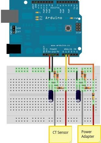
Step Two – Assemble the electronics
The electronics consist of the sensors (which produce signals proportional to the mains voltage and current) and the sensor electronics that convert these signals into a form the Arduino is happy with.
For a circuit diagram and detailed discussion of sensors and electronics see:
CT Sensors – Interfacing with an Arduino
Measuring AC Voltage with an AC to AC power adapter
Assemble the components as in the diagram above.
Step Three – Upload the Arduino Sketch
The Arduino sketch is the piece of software that runs on the Arduino. The Arduino converts the raw data from its analog input into a nice useful values and then outputs them to serial.
a) Download EmonLib from github and place in your arduino libraries folder.
Download: EmonLib
For more detail: How to build an Arduino energy monitor – measuring mains voltage and current
- What components are required to build the energy monitor?
You need an Arduino, a 9V AC-AC power adapter, various resistors including 100kOhm and 470kOhm, capacitors, a CT sensor SCT-013-000, a burden resistor, a breadboard, and single core wire. - How does the device measure voltage safely?
The setup uses an AC to AC power adapter to measure voltage, ensuring no high voltage work is needed. - Can this project calculate power factor?
Yes, the energy monitor can calculate real power, apparent power, power factor, rms voltage, and rms current. - Where should I download the EmonLib library?
You should download EmonLib from github and place it in your arduino libraries folder. - What type of sensor is used for current measurement?
A clip on CT sensor, specifically the SCT-013-000, is used to measure current. - Does the calculation happen in the analog domain?
No, all calculations are done in the digital domain on an Arduino. - What is the purpose of the burden resistor values?
The burden resistor value depends on the supply voltage, being 18 Ohms if the supply is 3.3V or 33 Ohms if the supply is 5V. - How does the Arduino sketch process the data?
The sketch converts raw data from analog inputs into useful values and outputs them to serial.