Summary of Simple Arduino light meter
This Arduino project functions as a light meter using a photo-transistor to control eight red LEDs via BC547 transistors. The system reads light intensity from an analogue pin, calculates brightness levels by dividing the sensor range, and illuminates corresponding LEDs to visualize ambient light conditions.
Parts used in the Simple Arduino Light Meter:
- Arduino board
- Photo-transistor
- 10 red LEDs
- 10 BC547 transistors
- 2.2K resistors
- 560 ohm current limiting resistors
- 12 volt source
This Arduino project is a simple light meter using a photo-transistor. An LDR would be more appropriate but the photo-transistor is what I has spare at the time. On the other hand the photo-transistor is sensitive to infrared, so its handy for testing remote controls.
The project consists of 10 red LEDs driven by 10 BC547 transistors although any general purpose transistor will do. The base of each transistor is connected to the Arduino board digital pins D0 through to D7 via a 2.2K resistor. The LEDs are connected to a 12 volt source with current limiting resistors of 560 ohms.
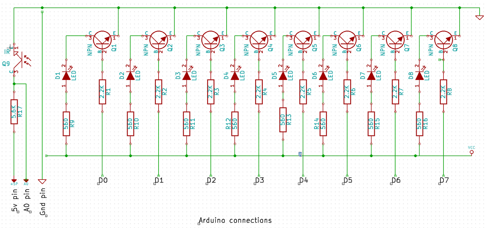
The input is provided by a photo-transistor connect to the Arduiono’s analogue input on analogue pin 0. The range of the input for the photo-transistor is 0 (full light) to 1023 (full dark), 1024 in total. This output is divided by 128, that is the full range (1024) divided by the number of LEDs (8). As the result is cast as a floating point, we round it up to the nearest integer. So 7.5 become 8. Finally we subtract this result from the total number of LEDs.
A simple for loop is used to enumerate the result and light/extinguish the appropriate number of LEDs. The source below:
int sensorPin = A0;
float sensorValue = 0;
int leds = 8;
int result = 0;
int divisor = 128;

void setup()
{
  PORTD = B00000000;
  pinMode(0,OUTPUT);
  pinMode(1,OUTPUT);
}

void loop() {
  sensorValue = analogRead(sensorPin);
  result = leds - round(sensorValue / divisor);
  for(int i = 0;i < leds;i++) {
    if(i < result) {
      digitalWrite(i,HIGH);
    } else {
      digitalWrite(i,LOW);
    }
  }
}
The results can be seen in this quick video showing how the LEDs react when a torch is brought near the photo-transistor:
For more detail: Simple Arduino light meter
- Why was a photo-transistor chosen over an LDR?
The author used a photo-transistor because they had spares at the time, though an LDR would be more appropriate. - Can this project test remote controls?
Yes, the photo-transistor is sensitive to infrared, making it handy for testing remote controls. - How many LEDs are driven in this project?
The project consists of 8 red LEDs driven by 8 transistors, despite mentioning 10 initially. - What is the input range for the photo-transistor?
The range is 0 for full light to 1023 for full dark, totaling 1024 values. - How is the sensor value calculated to determine LED count?
The output is divided by 128, rounded up to the nearest integer, and subtracted from the total number of LEDs. - Which digital pins connect to the transistor bases?
The base of each transistor connects to Arduino digital pins D0 through D7 via a 2.2K resistor. - What voltage source powers the LEDs?
The LEDs are connected to a 12 volt source with current limiting resistors. - Does the code use a loop to control the LEDs?
Yes, a simple for loop is used to enumerate the result and light or extinguish the appropriate number of LEDs.