Summary of 8 LED Chaser with 74HC595 8 Bit Shift Register using arduino
This tutorial demonstrates creating an 8-LED Cylon/Knight Rider scanner effect using a 74HC595 shift register to conserve Arduino pins. The project involves wiring the IC for power, data, clock, and latch signals, connecting eight LEDs with current-limiting resistors, and uploading custom code to drive the light sequence.
Parts used in the 8 LED Chaser:
- Arduino Uno (or compatible clone)
- Jumper Wires
- 1x 74HC595 8 Bit Shift Register
- 1x Breadboard
- 8x 220 Ohm Resistors
- LEDs (LED bar graph used)
Have you wanted to make a sweet Cylon/Knight Rider (Larson) Scanner effect? But you don’t want to use up all of your Arduino IO pins? Well, you can make a nice 8 LED Scanner with a shift register IC.

In this tutorial we’ll be using the 74HC595 8 Bit Shift Register, and this is what we’ll be making;
Parts Required:
Arduino Uno (Or Arduino compatible clone)
Jumper Wires (Various colours and lengths)
1x 74HC595 8 Bit Shift Register
1x Breadboard
8x 220 Ohm Resisters
Step 1: Get Ready to Shift
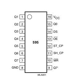
Take your shift register and place it on your breadboard over the IC gap, now take your black jumper wires and you’ll want to ground the IC, taking note where the notch is (Pin 1 is usually left of the notch) you’ll want to ground pin 8 and pin 13.
Step 2: Power, Data, Clock and Latch
Take your red jumper wire and wire in the voltage to pins 10 and 16.
Take your blue wire (data) and connect it to pin 14, the yellow (clock) to pin 11 and green (latch) to pin 12 on the IC respectfully.
Then take your LED’s (I’m using an LED bar graph for size) and place them over the IC gap.
Step 3: Let there be LED Light!
Now take some more jumper wires and start to wire up the LED’s, Start with IC pin 15, then from pin 1 to pin 7.
Then take your 220 Ohm resistors and wire them from the other side of the LED’s to the ground rail.
Step 4: Arduino Time!
Bring your Arduino over and hook it up to your PC and load in this code.
int clockPin = 12; //IC Pin 11, Yellow Jumper
int dataPin = 11; //IC Pin 14, Blue Jumper
int latchPin = 8; //IC Pin 12, Green Jumper
For more detail: 8 LED Chaser with 74HC595 8 Bit Shift Register
- How can I make a Cylon scanner without using many Arduino IO pins?
You can use a 74HC595 8 Bit Shift Register to create an 8 LED Scanner. - What is the purpose of grounding pin 8 and pin 13 on the IC?
These pins are grounded to prepare the shift register for operation. - Which wires connect to pins 10 and 16 on the IC?
A red jumper wire connects voltage to pins 10 and 16. - How do I connect the data signal to the 74HC595?
Connect a blue wire carrying data to pin 14. - Which color wire connects to the clock pin?
The yellow wire connects to pin 11 for the clock signal. - Where should the green latch wire be connected?
The green wire connects to pin 12 for the latch signal. - How are the LEDs wired to the shift register pins?
LEDs are connected starting from IC pin 15, then from pin 1 to pin 7. - Why are 220 Ohm resistors used in this project?
They are wired from the other side of the LEDs to the ground rail to limit current. - What code setup is required for the Arduino?
You must define clockPin as 12, dataPin as 11, and latchPin as 8.