
Summary of arduino based distance sensor using arduino
This tutorial outlines building a standalone Arduino-based distance sensor using an HC-SR04 ultrasonic module to measure obstacles in centimeters. The system utilizes an ATmega328 microcontroller and a 16x2 LCD for display, configured as a standalone circuit without a programmer.
Parts used in the Distance Sensor Project:
- HC-SR04 Ultrasonic Distance Sensor
- ATmega328 Microcontroller (or compatible Atmega chip)
- Arduino Programming Kit
- 16*2 LCD Display
- 10kOhm Variable Resistor
Here is a simple tutorial to build a Distance sensor which will show the distance from the distance sensor HC-SR04 ( Or any other compatible devices) to the wall or obstacles in front of the sensor in CentiMeters.
This project uses a HCR-SR04 distance sensor and atmega 328 or any other atmega chip which is programmed using a arduino programming kit, SO the project is based on arduino. But our final Circuit will be a standalone circuit without attached arduino programmer.
Hardware Used:
It is a simple Ultrasonic ranging module.
quiescent current : <2mA
effectual angle: <15°
ranging distance : 2cm – 500 cm
sequence chart
We can send a short ultrasonic pulse at t1 , and if any obstacles is there the received ultrasonic signal is converted to an electrical signal as Echo. If a 10μs width trigger pulse is sent to the signal pin, the Ultrasonic module will output eight 40kHz ultrasonic signal and detect the echo back. The measured distance is proportional to the echo pulse width and can be calculated by the formula above. If no obstacle is detected, the output pin will give a 38ms high level signal.
2> Arduino
Either a Arduino Board or a Arduino IC( Atmgea 328 , Atmega 128 , Atmega 8 etc ) with a programmer is used. To know more about Arduino visit the official arduino site http://arduino.cc
3> 16*2 LCD
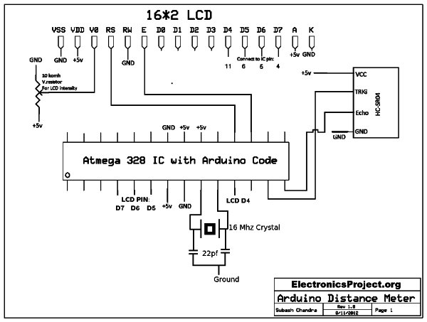
Wiring:
SO If you are going to use arduino board then please connect devices as following:
FOR LCD:
* LCD RS pin to digital pin 12
* LCD Enable pin to digital pin 11
* LCD D4 pin to digital pin 5
* LCD D5 pin to digital pin 4
* LCD D6 pin to digital pin 3
* LCD D7 pin to digital pin 2
* LCD R/W pin to ground
* 10Komhs Variable resistor with two ends to +5v and ground and the middle wipper ti LCD pin VO.
For more detail: arduino based distance sensor
- What is the ranging distance of the HC-SR04 sensor?
The ranging distance is between 2cm and 500 cm. - How does the sensor calculate distance?
The measured distance is proportional to the echo pulse width and can be calculated by a specific formula. - What happens if no obstacle is detected?
If no obstacle is detected, the output pin will give a 38ms high level signal. - Can this project work without an Arduino board?
Yes, the final circuit can be a standalone circuit without an attached Arduino programmer. - Which pins are used for the LCD data connection?
LCD D4 connects to pin 5, D5 to pin 4, D6 to pin 3, and D7 to pin 2. - Where should the LCD R/W pin be connected?
The LCD R/W pin should be connected to ground. - How is the variable resistor wired for the LCD?
The two ends connect to +5v and ground, while the middle wiper connects to LCD pin VO. - What trigger pulse width is sent to the signal pin?
A 10μs width trigger pulse is sent to the signal pin.
