In this project, we will learn how to control the brightness of LED via an I/O port (with PWM output capability) and a touch display slider. The 4Duino resistive touch display is used as a means for a graphical interface to control the intensity of the LED. Since the 4Duino itself has an LED on pin D13 with PWM output capability, you may use the LED to conduct this project for convenience.
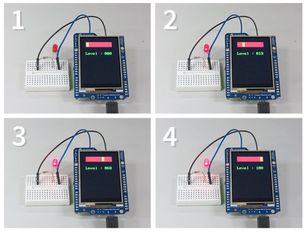
A LED (light emitting diode) works on the basic principle that when potential difference is applied across the anode and cathode, light is emitted. The higher the potential difference, the brighter the LED shines, therefore PWM (pulse width modulation) allows us to control how much potential difference and therefore the brightness of the LED. A PWM signal is an analog signal emulated by using digital control as a means to create a square wave, a signal switched between on and off.
LEDs being diodes have polarity and will only work if current flows from the anode to the cathode, therefore positive must always be connected to the anode and ground to the cathode. The longer lead of the LED is the anode whilst the shorter lead is the cathode. A resistor is typically placed before the anode in order to lower the current flowing through the led. This will extend the lifespan of the LED and dim the brightness to a level that is more comfortable to look at.
Note: If you end up clipping the leads, the anode lead can be found by looking inside the led and examining the metal contacts. The larger contact is the cathode, and the side of the cathode will be flat on the outside.
HOW IT WORKS
COMPONENTS
If not using onboard D13 LED you will require:
- LED
- 220Ω Resistor (Used to avoid burning out LED. 5V supplied from the I/O port is too much voltage across an LED)
- Jumper cables
- Micro USB cable
IMPLEMENTATION
Step 1: Build
Build the circuit as shown in the following diagram and schematic.
Step 2: Program
Workshop 4 – 4Duino Basic Graphics environment is used to program this project. (The same could be implemented in the latest Arduino IDE)
This project requires the Arduino IDE to be installed as Workshop calls the Arduino IDE for compiling the Arduino sketches. The Arduino IDE however is not required to be opened or modified to program the 4Duino.

Open this file using Workshop 4.
Note: Download the project here.
Step 3: Comms Port
Connect the 4Duino to the PC using µUSB cable.
Then navigate to the Comms tab and select the Comms port to which the 4Duino connected.
Read more: 4Duino LED Brightness Control