
Summary of LM3916 LED bargraph/ VU meter
This kit utilizes the LM3916 VU bargraph driver chip to create an audio meter or voltage indicator. It features a 10-segment constant current driver with internal reference voltages and comparators. The design supports both bargraph and single-dot display modes, controlled by jumpers and resistor values. While optimized for audio applications using the LM3916, it is compatible with LM3914 and LM3915 for linear or logarithmic responses. The board operates at 5V or lower and includes provisions for chaining multiple units.
Parts used in the LM3916 Audio Meter Kit:
- LM3916 VU bargraph driver chip
- R6 placeholder resistor (for voltage divider or filter)
- R3 jumper/resistor (for trigger point offset)
- R2 resistor (set to 0 ohms for audio input)
- R5 resistor (required for chaining multiple units)
- P1 and P2 connectors (for chain signals)
- P5 jumper (enables bargraph mode)
- LED array (10 segments)
- Precision resistor network
Brief description:
This kit builds on a famous LM3916 VU bargraph driver chip from TI/National semiconductor. The chip is essentially a constant current 10 segment driver fed by an array of comparators. It also provides internal reference voltage to set the rail of the precision resistor network feeding the comparator reference inputs. A signal coming in then determines how many signals are lit. Depending on the mode selected, either bargraph or a single dot is displayed. This particular kit is using LM3916, optimized for audio meter applications but could also be used with LM3914 and LM3915 parts to get linear and log response respectively (mainly set by the individual resistance values of internal divider networks).
Design features and notes:
- R6 is a placeholder should you require a voltage divider or a filter on the input
- R3 is normally a jumper, but could be used to offset the trigger points up if needed (If building a battery monitor for example, where you need more attention in a narrow voltage range)
- When using with audio input, set R2 to 0 ohms. That effectively moves voltage reference adjust pin to ground, setting top comparator rail to 1.25V
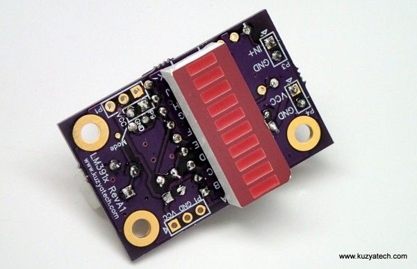
- R5 is only needed when connecting multiple units in a chain. Use P2 and P1 to get at the signals needed for that
- Jumper P5 enables bargraph mode when installed.
- The board will run happily at 5V or even lower. If you change LED current setting and run from higher supply voltage, keep an eye on power dissipation in the driver. (See page 2 of the datasheet for further details)
Testing:
The better way:
The most controlled and convenient test signal source is a good signal generator. I’ve been using a slope mode on my Rigold DG1022, with very slow (300-500mHz) frequency and and varying symmetry to obtain the effects in the test video
For more detail: LM3916 LED bargraph/ VU meter
-
What is the primary function of the LM3916 chip in this kit?
The chip acts as a constant current 10 segment driver fed by an array of comparators with an internal reference voltage. -
How do you switch between bargraph and dot display modes?
Installing jumper P5 enables bargraph mode, while removing it selects the single dot display mode. -
What value should R2 be set to when using an audio input?
R2 should be set to 0 ohms to move the voltage reference adjust pin to ground, setting the top comparator rail to 1.25V. -
When is the R5 resistor required in this circuit?
R5 is only needed when connecting multiple units together in a chain. -
Can this kit be used with chips other than the LM3916?
Yes, it can use LM3914 for linear response or LM3915 for log response depending on resistance values. -
What is the recommended operating voltage for this board?
The board runs happily at 5V or even lower supply voltages. -
What is the best way to test this kit effectively?
The most controlled method is using a signal generator with slope mode at a slow frequency like 300-500mHz.
