
Summary of 3 Simple Ways of Programming an ESP8266 12X Module
This article guides users on programming ESP12 modules for custom PCBs, offering two primary methods: using a "Frog" pin programmer or a generic USB-to-serial converter. It details necessary software setup via Arduino IDE and outlines specific hardware requirements like pull-up resistors and 3.3V power supplies. The guide explains how to manually trigger programming mode by manipulating GPIO 0 and RST pins and provides exact wiring configurations and board settings for successful sketch uploads.
Parts used in the Programming an ESP8266 12X Module Project:
- ESP12 module
- Wemos D1 Mini development board (optional)
- Adafruit Feather Huzzah (optional)
- Frog Pin Programmer (Aliexpress or Tindie version)
- USB to Serial Converter (e.g., PL2303)
- 10K Resistors
- External 3.3V Power Supply
- Capacitor
- Buttons for GPIO 0 and RST
If you are not familiar with ESP8266 micro controller, I really feel you have been missing out! These things are incredible: they are cheap, powerful and best of all have built-in WiFi!
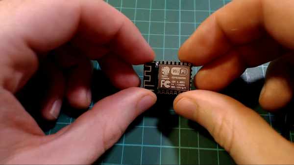
ESP8266 started their journey out as a WiFi add on board for more traditional Arduino boards but shortly after, the community realized the power of them and added support to be able to program directly with the Arduino IDE.
These days if you are looking to use an ESP8266 for your project I would recommend using a development board such as the Wemos D1 Mini* ($2.50 delivered!!) or Adafruit Feather Huzzah. These boards have all the usable pins broken out, are easily programmable via their micro USB connector and have a built in 3.3V regulator.
But what if you want to use an ESP8266 in a project with a custom PCB? The easiest way is to use an ESP12 module, and in this Instructable I’ll show you a couple of simple ways of programming them.
* = Affiliate Link
Step 1: Check Out the Video!
Here is a video with all the info contained in the Instructable if you like to check it out.
On my channel I do a lot of work with ESP8266s so my channel in general maybe worth checking out if that sort of stuff interests you!
Step 2: Pre-Step: Setup for Programming the ESP8266
If you have never used the ESP8266 or Arduino before, we will need to a little bit of software setup. I have a dedicated video for this. It’s only 5 minutes long and goes through everything you need to setup.
If videos are not really your thing, check out lesson 2 of Becky’s awesome IoT Class, it goes over everything you need as well.
Before you move to the next section you should be able to upload a simple sketch to an ESP8266 (such as the blink example mentioned in both the video and Becky’s lesson)
Step 3: Method 1: “Frog” Pin Programmer
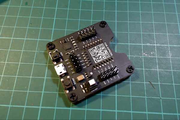
This is probably the easiest way to program an ESP12 module. You basically just pop the module into the board and then it behaves exactly like one of the development boards mentioned earlier. I selected the Wemos D1 Mini board from the boards drop down when programming.
There downsides to this method are:
- The programmer is a little bit expensive if you are only making a few boards.
- Boards can only be programmed this way before they are soldered to your PCB
The one I bought is from Aliexpress, but I believe the original designer is a user on Tindie called Fred. They were sold out at the time so I ended up going with the Aliexpress one, but I’ll link to both.
* = Affiliate Link
Step 4: Method 2: Using Basically Any USB to Serial Converter
For the next method we are going to manually put the ESP module into programming mode and then use basically any USB to serial converter to program the ESP8266, even this PL2303 one* that costs 50c delivered works!
Normal Operation:
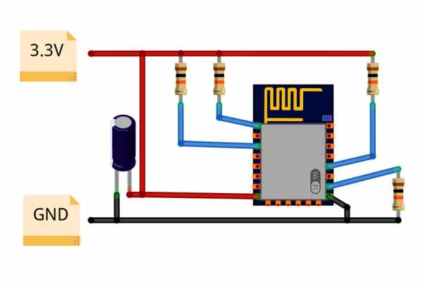
Before we get started on programming we first need to take a look at the what external components the ESP8266 needs to run. For normal operation an ESP-12 module needs the following
- EN, RST and GPIO 0 needs to be pulled high using a 10K resistor
- GPIO 15 needs to be pulled to Ground using a 10K resistor
- 3.3V power supply capable of about 250mA of current (A cap between VCC and GND is recommended)
With the above configuration the ESP8266 when powered on will be in Normal operating mode, so it will run whatever sketches you have programmed to it.
You can buy breakout boards for ESP-12 modules* that are really useful for testing out the different setups. The modules have the resistors setup for the EN and GPIO 15 pin, so you will still need to add the pull-up resistor for RST and GPIO 0,
Enabling Programming mode:
To get it into programming mode, GPIO 0 needs to be pulled low when the ESP is starting up. The easiest way to do this is to add buttons to GPIO 0 and the RST pin that connect to ground when pressed. Then to enable flash mode, you simply
- Hold down the GPIO 0 button
- Press the RST button
- Then let go of both buttons
You don’t need to perform this sequence at any particular time during the upload process or anything, once the ESP is in programming mode it will stay there til the next reset, so just perform the steps any time before uploading.
Programming with a USB to serial adapter:
Enabling program mode is only half the battle, now we need to actually program the module. Most USB to serial adapters can not provide enough current to the ESP8266 so it’s recommended that you power the ESP8266 using an external 3.3V source.
To wire up the programmer you need to connect the following pins (also shown in an image above):
- Connect TX of the programmer to RX of the ESP8266 (Not a typo, the connections are reversed)
- Connect RX of the programmer to TX of the ESP8266
- Connect Ground of the programmer to Ground of the ESP8266
To upload your sketch, do the following steps:
- Select the port number of your Serial adapter (Tools->Port)
- Enable programming mode on your ESP8266 as described above
- Click the upload button. (If it fails double check your wiring and try resting your board into programming mode again)
- Click the reset button when the upload has finished
Here are the board settings I used when uploading using this method:
- Board: Generic ESP8266 Module
- Flash Mode: DIO
- Flash Size: 4M (3M Spiffs)
- Reset Method: ck
- Flash Frequency: 40MHz
- Upload Speed: 115200
The last thing to note is the LED_BUILIN defintion for a generic ESP8266 module points to pin 1, but the built in LED of a ESP12 module is connected to pin 2 (It’s active low too just as an FYI). So if you are testing out a blink sketch you will need to use the number 2 rather than LED_BUILTIN
* = Affiliate Link
Source: 3 Simple Ways of Programming an ESP8266 12X Module
- What is the easiest way to program an ESP12 module?
The easiest way is to use a Frog Pin Programmer which allows the module to behave like a standard development board. - Can I use any USB to serial converter for this project?
Yes, you can use basically any USB to serial converter, even inexpensive ones like the PL2303. - How do I enable programming mode on an ESP12 module?
You must hold down the GPIO 0 button, press the RST button, and then release both buttons before uploading. - What external components are needed for normal operation of an ESP12 module?
You need 10K resistors pulling EN, RST, and GPIO 0 high, a 10K resistor pulling GPIO 15 to ground, and a 3.3V power supply. - Does the USB to serial adapter provide enough power for the ESP8266?
No, most adapters cannot provide enough current, so it is recommended to power the ESP8266 using an external 3.3V source. - How should the TX and RX pins be connected between the programmer and the ESP8266?
You must connect the TX of the programmer to the RX of the ESP8266 and the RX of the programmer to the TX of the ESP8266. - Which pin is the built-in LED connected to on an ESP12 module?
The built-in LED is connected to pin 2 and is active low. - When can I perform the sequence to enable flash mode?
You can perform the steps at any time before uploading because the ESP stays in programming mode until the next reset.
