I’ve made an iButton garagedoor opener and logger.
On a Dutch (kind of) eBay (www.marktplaats.nl) I found some iButtons and readers very cheap. I had no idea what to do with them, but I bought them anyway.
My garage opens with a push on a button, so it must be possible to get that working with the iButton.

I also found some really cheap (0,50 euro) displays, so it would be nice if I also can make a screen to show me who entered when.
The project is now existing in three parts:
- The iButton opening the door
- A clock keeping track of times and dates
- A screen showing the information
So to keep things understandable I try first to figure out the three parts separately.
Step 1: You will need
Parts
- iButton(s)
- iButton reader
- Arduino
- 2 push buttons
- power supply
- 2 10 kOhms resistors
- 220 Ohms resistor
- 2,2 kOhms resistor
- 10 kOhms potmeter
- LCD-display with HD44780 controller
- NPN transistor
- relais
- 1N4001 diode
- some wire
- PCB
Tools
- soldering iron
- solder
- snips
- breadboard
- computer with Arduino software
- a LED
Step 2: IButton opening the door
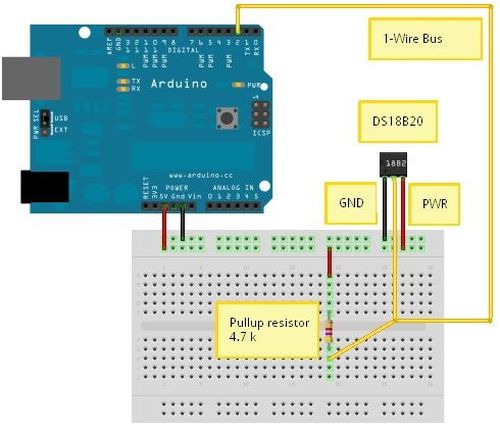
So I bought the parts. Now I had to find out how the things work. Trough the Arduino-site (www.arduino.cc) I found the “Fridzing” drawing on http://tushev.org/articles/electronics/42-how-it-works-ds18b20-and-arduino. I also found the 1-Wire library there. 1-Wire is the name of the communication method used by the iButtons.
With this drawing and the library it was easy to wire everything and get it running.
How to wire up
According to the schematics, I took my Arduino, a breadboard, the iButton reader, a 2,2 kOhms resistor, three wires and a LED.
I wired it a little bit different than the drawing. My iButton reader had only two wires.
- a wire from 5V on the Arduino to the + lane on the breadboard
- the resistor from the + lane to the first lane on the breadboard
- a wire from the first lane (where also the resistor is) to pin 2 on the Arduino
- the grey wire of the iButton reader to the first lane of the breadboard
- the black wire of the iButton reader to the – lane of the breadboard
- a wire from the – lane to the GND of the Arduino
- put the LED with the long leg (anode) in pin 13 of the Arduino and the short leg (cathode) in GND
Now I run the sketch (code) like shown in iButton.pde and entered the code like it is shown in small letters on the iButton.
To be able to run this sketch, I first have to download the library from the site shown above and put this in the [library] folder in the [Arduino] folder. If you don’t have a [library] folder in your [arduino] folder, you should make one. Next you have to restart the Arduino program for it to know the new library is there. (trust me, if you don’t restart the program, you can try, and try, and try, but it will not work)
If I put the right iButton in the reader, the LED will light up for a short moment. If I put in the wrong iButton the LED won’t light up.
The first part is working now. If I connect pin 13 to a relays in stead of a LED and I connect that relays to the button that open my garage door, my garage door will probably open.
Step 3: The garage door
Before I went any further I first wanted to check wether the button opening my garage really worked by just connecting two wires. To be sure that I didn’t kill myself, I first measured how much volts are going trough the button. I simply removed the button from the wall and put my multimeter on the two screws on the back. I had a reading of 21 V DC, so that might bite, but probably won’t kill me if I accidentally touch it.
Now I simply connected the two screws with a piece of wire and the door opened.
Adding the relay
My theory worked so now it was time to add the relay to my design. On the “Fritzing” drawing you can see how I did that.
I moved the iButton to port 12 to make more room on the Arduino to ad the clock and the LCD later on.
The Arduino will switch the transistor (I used a BC338 that I had laying around, but any 5V NPN general purpose will probably do) and the transistor will switch the relay. The green wires going from the relay will be connected to the screws on the back of the button that opens the garage.
The diode should be there to help the relay. (I’m not sure why anymore, but just put it there, the relay will live longer)
- iButton(s)
- iButton reader
- Arduino
- LCD-display with HD44780 controller
- NPN transistor
For more detail: The iButton garage-door opener using an Arduino