To Learn about the basic LED usage practice, read here.
What is a RGB LED?
With an RGB (Red Green Blue) LED you’ll be able to produce any colour that is flashing everyone’s eyes. At first glance, RGB LEDs look just like regular LEDs, however, inside the usual LED package, there are actually three LEDs, one red, one green and yes, one blue. By controlling the brightness of each of the individual LEDs you can mix pretty much any color you want.
To Learn about the basic LED usage practice, read here.
At first using an RGB LED with Arduino seems quite complex, but it quite quickly becomes clear that its no more difficult than controlling one of their single colour counter parts.
We mix colors just like you would mix audio with a ‘mixing board’ or paint on a palette – by adjusting the brightness of each of the three LEDs. The hard way to do this would be to use different value resistors (or variable resistors) as we played with in lesson 2. That’s a lot of work! Fortunately for us, the Arduino has an analogWrite function that you can use with pins marked with a ~ to output a variable amount of power to the appropriate LEDs.
Required Parts for this Tutorial:
RGB LED (common anode)
- A common anode RGB LED is nothing more complicated than three one colour LEDs (one red, one green, and one blue) housed in a single package.
- Rather than having 6 leads (a cathode and anode for each LED) it has only 4 one cathode for each colour, and one common anode. (see the schematic diagram below)
- A common anode RGB LED is the most popular type. It is most commonly found in either a 5mm bulb size or as a 5mm pirahna form factor.
Current Limiting Resistors (270 ohm) (red-purple-brown)
- Most LEDs are designed to work with a voltage between 1.5v and 3v. As most microcontrollers (including the Arduino) operate on 5 volts a current limiting resistor is required.
- Consult your LEDs datasheet for maximum ratings but we like to use 270 ohm resistors. This limits the current to ~20mA, well within most LEDs and microcontroller ratings.
Arduino Microcontroller & Breadboard
- A great open source microcontroller platform (for more details visit arduino.cc)
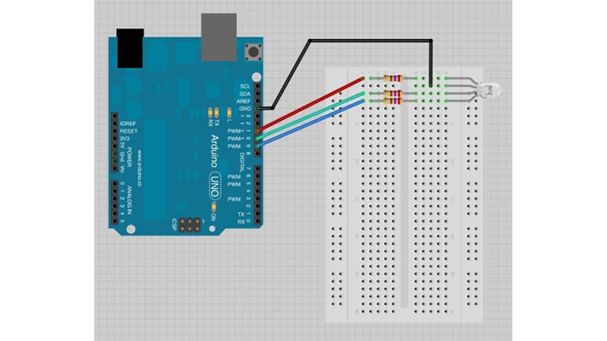
How to Connect RGB LED with Arduino
The common negative connection of the LED package is the second pin from the flat side of the LED package. It is also the longest of the four leads. This lead will be connected to ground.
For testing purposes, check your LED datasheet for its pin-out or below are the two most common RGB LED form factors and pin-outs. The following is an example:
Wire up the Test Schematic (below)
- Connect a current limiting resistor (270Ω) to each of the three cathodes
- Connect the common anode to 5V
- Test each color by connecting its current limiting resistor to ground
- Experiment with colour mixing a little by powering multiple elements at once
Each LED inside the package requires its own resistor to prevent too much current flowing through it. The three positive leads of the LEDs (one red, one green and one blue) are connected to Arduino output pins using these resistors.
Arduino
For more detail: RGB LED with Arduino 101