Summary of Oscilloscope / Logic Analyzer using Arduino
This project uses an Arduino to capture multiple input signals and send the data via USB to a host computer running a Processing program that visualizes the inputs on-screen. The Arduino acts as a flexible data acquisition device, relaying analog or digital signals for software-based analysis. While offering ease of use and adaptability, the system is limited by Arduino’s 10-bit ADC resolution and sampling rate (~5 kHz), making it suitable for basic signal monitoring but not as powerful as professional oscilloscopes or logic analyzers.
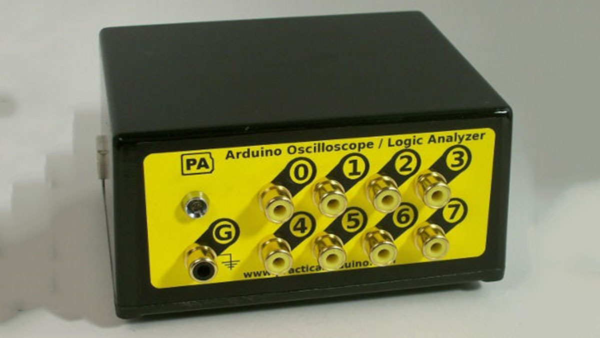
Parts used in the Oscilloscope / Logic Analyzer using Arduino:
- Arduino microcontroller board
- USB cable
- Host computer (Windows, Linux, or MacOS)
- Processing programming environment/software
- Input signals (analog and/or digital)
One of the frustrating things about developing and debugging electronic circuits is that you can’t look inside the circuit to see what is happening. Even with a circuit laid out before you on a workbench and powered up it may seem like you’re in the dark, unable to figure out why an input change or alteration in one part of the circuit isn’t having the effect you expected. Sometimes it can feel like you’re working with a blindfold on.
In this project we use an Arduino to capture multiple input values and pass them via the USB connection to a host computer running a program that deciphers the values and displays them on-screen. Because the Arduino itself is not providing any particular intelligence and simply passes on any values it reads, this project is very flexible and the behavior of the system can be changed simply by altering the software that runs on your computer. This opens up a wide range of possibilities for using the same basic hardware to process and visualize analog data, parallel digital data, and serial digital data.
The visualization program demonstrated in this project is written in Processing, a sister project to Arduino that is designed to allow rapid development of visual programs in the same way that Arduino allows rapid development of physical programs. Processing runs on Windows, Linux, and MacOS.

However, this simple approach has some major limitations in terms of both sample rate and resolution so don’t expect an Arduino-based system to rival a professional-grade oscilloscope or logic analyzer. The analog inputs on an Arduino operate by default at 10-bit resolution which provides a scale of 0 to 1023, while more advanced ADCs provide 12-bit resolution or higher. The Arduino analog inputs also take around 100 microseconds to take a reading, limiting the number of samples it can take per second and restricting it to much lower frequencies than a more advanced ADC.
The result is a system that will operate quite well at 10-bit resolution at up to somewhere in the region of 5KHz, depending on how many channels you are monitoring. Not great specs, but certainly better than nothing if you can’t afford a professional oscilloscope or logic analyzer.
For more detail: Oscilloscope / Logic Analyzer using Arduino