The WiFi Shield was delivered by Amazon.
The Arduino UNO Rev 3 was found at RadioShack…
First you need to load the last Arduino IDE (Ver 1.0.2) it has the necessary library to use the WiFi shield.
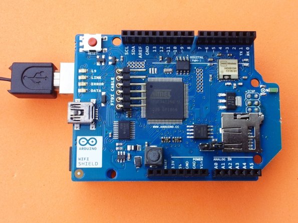 Tried the examples “Scan for available networks” and “WPA network example”
from:
http://arduino.cc/en/Guide/ArduinoWiFiShield
It works like a charm!
thanks Arduino Team…
Now some work is comming…
Thinking in some applications…
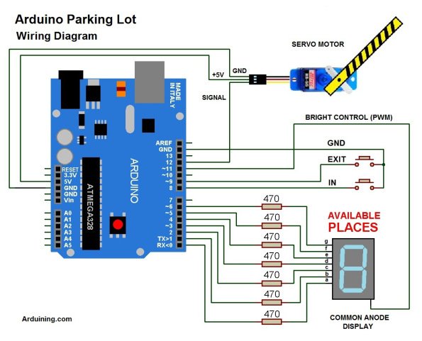
Here is the code:
/*ParkingL02.pde
Arduining.com 08 JUL 2012
Code used in the production of the Youtube material.
*/

#include <Servo.h>
Servo myservo;  // create servo object to control a servo

#define ServoM    12        //Connected to the servo motor.
#define Bright    11        //servo library disable PWM on pins 9 and 10.
#define Exit      9         //Pin connected to the EXIT button.
#define In        8         //Pin connected to the IN button.

#define BarLow    177       //Low position of the barrier.
#define BarUp     95        //Up position of the barrier.
#define CAPACITY  8         //Capacity of the parking lot.
#define INTEN     80        //Display intensity %

//Pins conections to segments (cathodes).
#define  segA  0
#define  segB  1
#define  segC  2
#define  segD  3
#define  segE  4
#define  segF  5
#define  segG  6

//Array with the segments to represent the decimal numbers (0-9).
byte segments[10] = {
// pgfedcba  <--- segments
  B00111111, // number 0
  B00000110, // number 1
  B01011011, // number 2
  B01001111, // number 3
  B01100110, // number 4
  B01101101, // number 5
  B01111101, // number 6
  B00000111, // number 7
  B01111111, // number 8
  B01101111  // number 9
};

void setup(){
  myservo.attach(ServoM);          // attaches the servo.

  pinMode(Exit, INPUT);           // set "EXIT" button pin to input
  pinMode(In, INPUT);             // set "IN" button pin to input
  digitalWrite(Exit, HIGH);       // Connect Pull-Up resistor.
  digitalWrite(In, HIGH);         // Connect Pull-Up resistor.
  pinMode(segA,OUTPUT);
  pinMode(segB,OUTPUT);
  pinMode(segC,OUTPUT);
  pinMode(segD,OUTPUT);
  pinMode(segE,OUTPUT);
  pinMode(segF,OUTPUT);
  pinMode(segG,OUTPUT);
  pinMode(Bright,OUTPUT);
  analogWrite(Bright,255*INTEN/100);
  myservo.write(BarLow);          //Barrier in the low position
//  delay(1000);
}

int  Available= 9;                    // Number of places available.

//================================================================
void loop(){
Display(Available);
if(digitalRead(In)==0)
{
  if(Available != 0){
    Available--;
    myservo.write(BarUp);
    delay(3000);
    myservo.write(BarLow);
    }
  }
if(digitalRead(Exit)==0)
{
  if(Available != CAPACITY){
    Available++;
    myservo.write(BarUp);
    delay(3000);
    myservo.write(BarLow);
    }
  }
}

/*-------------------------------------------------------------------
Put the segments according to the number.
--------------------------------------------------------------------*/
void Display(int number){
byte segs =  ~segments[number];        //"~" is used for commom anode.

digitalWrite(segA, bitRead(segs, 0) );
digitalWrite(segB, bitRead(segs, 1) );
digitalWrite(segC, bitRead(segs, 2) );
digitalWrite(segD, bitRead(segs, 3) );
digitalWrite(segE, bitRead(segs, 4) );
digitalWrite(segF, bitRead(segs, 5) );
digitalWrite(segG, bitRead(segs, 6) );
}
LaunchPad and Energia ( StopWatch )
This is a simple project using the LaunchPad from Texas Instruments and Energia (Arduino-like IDE).
The Launchpad version 1.5 comes with the MSP430G2553 microcontroller, it has a hardware UART (use the jumpers as shown in the image).
This is a funny and very low cost project.
The LaunchPad measures time (in microseconds) .The car travels a fixed distance between contacts (10 Cms).
Time is measured using START and STOP contact switches.
Contact switches are implemented using neodymium magnets.
You’ll need small nails, miniature neodymium magnets and colors headed pins to assemble the switches.
Here is the code used:
/* Cronometer01.ino
  Arduining.com 25/AUG/12
  Used in the LaunchPad V-1.5 with the MSP430G2553
  Measuring time between the signals of START and STOP  in microseconds.
  The result is sent serial at 9600 bauds.

  GREEN LED on indicate READY TO START.
  RED LED on indicate MEASURING TIME.
  RED LED blinking indicate MEASURE DONE.

  Push RESET in the LaunchPad to repeat the measurement.
 */
#define START  11     //Pin P2.3
#define STOP   12     //Pin P2.4
unsigned long time;

void setup() {
  pinMode(START,INPUT_PULLUP);  //internal pull-up
  pinMode(STOP,INPUT_PULLUP);   //internal pull-up
  pinMode(GREEN_LED, OUTPUT);
  pinMode(RED_LED, OUTPUT);
  Serial.begin(9600);
}

void loop() {
  Serial.println("READY");
  digitalWrite(GREEN_LED, HIGH);   // set the GREEN LED on
  digitalWrite(RED_LED, LOW);      // set the RED LED off

  while(!digitalRead(START)){}
  time = micros();
  digitalWrite(GREEN_LED, LOW);    // set the GREEN LED off
  digitalWrite(RED_LED, HIGH);     // set the RED LED on

  while(!digitalRead(STOP)){}
  time = micros()-time;
  digitalWrite(RED_LED, LOW);      // set the RED LED off
  Serial.print(time);
  Serial.println(" Microseconds");

  while(1){                        // Blink to indicate END.
    delay(900);                    // wait 0.9 second
    digitalWrite(RED_LED, HIGH);   // set the RED LED on
    delay(100);                    // wait 0.1 second
    digitalWrite(RED_LED, LOW);    // set the RED LED off
  }

}
unsigned long time;
void setup() {
pinMode(START,INPUT_PULLUP); //internal pull-up
pinMode(STOP,INPUT_PULLUP); //internal pull-up
pinMode(GREEN_LED, OUTPUT);
pinMode(RED_LED, OUTPUT);
Serial.begin(9600);
}
void loop() {
Serial.println("READY");
digitalWrite(GREEN_LED, HIGH); // set the GREEN LED on
digitalWrite(RED_LED, LOW); // set the RED LED off
while(!digitalRead(START)){}
time = micros();
digitalWrite(GREEN_LED, LOW); // set the GREEN LED off
digitalWrite(RED_LED, HIGH); // set the RED LED on
while(!digitalRead(STOP)){}
time = micros()-time;
digitalWrite(RED_LED, LOW); // set the RED LED off
Serial.print(time);
Serial.println(" Microseconds");
while(1){ // Blink to indicate END.
delay(900); // wait 0.9 second
digitalWrite(RED_LED, HIGH); // set the RED LED on
delay(100); // wait 0.1 second
digitalWrite(RED_LED, LOW); // set the RED LED off
}
}
For more detail: New Arduino WiFi Shield (Testing)