If you can’t explore the Moon or Mars … you can always explore your neighborhood!
The main goal of this project is to alter a remote controlled vehicle and control it via
Internet Telerobotics using the Mobile Telephone Network (WWAN – Wireless Wide
Area Network) 3.5G or 4G (Long Term Evolution) and as an alternative you can always
use WiFi networks.
For this challenge it is necessary to make some modifications to a remote-control
car, adapting and equipping it with the necessary software and hardware in order to
achieve the objectives stated above
Step 1: Earth Exploration Videos
This first video shows th 3D Sketch of the Mobile Earth Rover.
Now form 3D to the real word, this second video shows some parts of the building
stage and some initial test runs using the 3.5G network. The vehicle is equipped
with a boom camera arm that allows 1st and 3rd person viewing, the camera also
preforms pan and tilt movements.
This last video shows a test run in various places, where the maximum distance
from the control room to the vehicle exceeds 1 Kilometer :
all over the place, as long as you have 3.5G coverage, the maximum i dared to go was
about 1 km from base without supervision.
Step 2: The Idea
The main goal is to be able to remotely control an RC vehicle using the mobile phone
Network (3.5G or 4G) controlled via Internet Telerobotics in order to explore your
neighborhood, or let other people in remote locations do the exploring!
This goal is possible by equipping an RC Truck with an on-board computer capable of
connecting itself to the 3.5G/4G Network, thus making it ready to be controlled by any
one with a computer with an Internet connection.
Note:
– In the image above, the hexagons correspond to the mobile phone network coverage
area.
– The RC’s Truck Transmitter is used as an USB plug and play device, to control the RC.
uppliers:
– Asus EeePc , Web camera – Staples
– Traxxas E-Maxx, Batteries, Springs – http://www.modelsport.co.uk
– Arduinos, Micro Servo Controller- http://www.coolcomponents.co.uk
– All kinds of Servo Motors – http://www.servoshop.co.uk
– LED’s and fixing supports – http://www.ultraleds.co.uk
– Metalic Barrings – RS Amidata
Project Costs:
– Around 1500$USD Total cost (in 2009)
Necessary tools and materials:
– Laser CNC router or Plasma CNC router
– Aluminum plate – size 1200x600x3mm (Form main chassis base and for the beams)
– Aluminum plate – size 400x400x1mm (For servo casing, Arudino casing, LED support, etc)
– Bolts – 100 units of 3mm (3M)
– Nuts – 200 units of 3mm (3M) (2 nuts per bolt for extra holding force)
– Several different sized screw drivers
– Several different sized pliers
– Metallic file (to trim the aluminum borders)
– Some sandpaper (for aluminum finishing)
– Paper face mask ( to avoid inhaling aluminum dust (highly toxic) )
– Some transparent aluminum varnish spray (for painting the aluminum to avoid
aluminum oxidation)
1. Cut out all the necessary aluminum parts form the aluminum plate (see photo of
all aluminum parts):
Instructions:
1.1 – Parts for holding/fixing the Arduino on board (see photos for more detail)
1.2 – Parts for holding/fixing the EeePC (see photos for more detail)
1.3 – Parts for holding/fixing the Pololu Micro servo Controller (see photos for more detail)
1.4 – Parts for holding/fixing the LED’s (see photos for more detail)
1.5 – Parts for holding/fixing the 3.5G/4G Modem (see photos for more detail)
1.6 – Parts for holding/fixing the 2 micro servos and 1 boom camera servo
1.7 – Parts for holding /fixing the Aluminum beams (see photos for more detail)
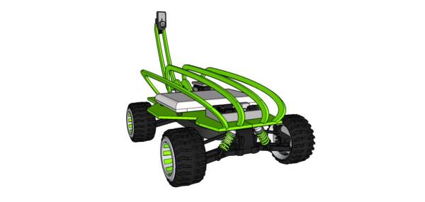
2. The aluminum base plate:
Instructions:
2.1 – Download the 2D design here: http://dl.dropbox.com/u/4302919/chassis_v15.cdr.
2.2 – Cut the aluminum plate using a laser CNC router.
2.3 – The design needs to be laser cut or Plasma CNC router or Laser CNC router.
2.3 – All small holes have 3mm diameter for allowing the bolts to fit.
2.4 – The center square hole in the middle of the plate is made in order to allow for the
motors to fit in between and lower the center of mass.
2.5 – The 4 small rectangular holes are for allowing cables to pass from one side of
the plate to the other.
3. The 4 aluminum beams:
Instructions:
3.1 – The aluminum beams allow for the protection of the electronic equipment
on-board the vehicle .
3.2 – The aluminum beams fit perpendicularity to the aluminum plate.
3.3 – The beams fit on the front and back of aluminum base (see photos)
4. The 2 “boom camera” aluminum beams:
Instructions:
4.1 – The 2 beams are screwed together spaced with 2.5cm apart (to create a
steady structure and to avoid propagation of vibration to the web camera)
4.2 – The camera is mounted on the end of the beams
4.3 – The boom camera beam is mounted on the rotary motor extension
4.4 – Because it is a moving part the beam has 2 docking stations, one in the
front and one in the back of the aluminum plate to allow the arm to rest
5. The pan tilt system:
Instructions:
5.1 – The pan tilt system is composed by 2 servo motors (see photo)
5.2 – The servos are mounted one on top of each other using small aluminum
cases (see photo)
6. Mounting the base aluminum plate to the aluminum beams:
Instructions:
6.1 – Mount the aluminum plate on board the vehicle.
6.2 – Isolate the center square hole with rubber to avoid the motor discharging on
the aluminum
6.3 – Tighten with bolts all the necessary aluminum parts in order to hold the
on-board Arduino.
6.4 – Mount the Arduino board on-board the vehicle.
6.5 – Tighten with bolts all the necessary aluminum parts in order to hold the
on-board computer (EeePc 901).
6.7 – Mount the on-board (EeePc 901) computer on the vehicle.
6.8 – Tighten with bolts the 4 protective aluminum beams
7. The boom camera motor system (this is the most complex mechanical aspect of the
mechanical work, see photos for more detail)
Instructions:
7.1 – Mount the boom camera motor inside a aluminum case and attach a cylindrical
extension inside 2 aligned bearings
7.2 – Attach the aluminum beams to the center of the cylindrical motor extension
After all the motors are attached inside of the aluminum casings make all the wire
connections mentioned in the previous step.
For more detail: Mobile Earth Rover One – 3.5G Exploration