Summary of Charlieplexing LEDs with an Arduino
This article explains Charlieplexing, a technique to control multiple LEDs using fewer microcontroller pins by leveraging diode polarity. Using an ATmega328 or Arduino with 5 pins, the project controls 12 LEDs (plus one extra) by activating specific pin combinations (HIGH/LOW/INPUT) to direct current through single LEDs at a time. The method relies on scanning LEDs rapidly if multiple need illumination simultaneously, ensuring total current stays within the microcontroller's 200 mA limit.
Parts used in the Charlieplexing LED Project:
- ATmega328 microcontroller
- Arduino board
- LEDs
- Breadboard
- Jumper wires (short orange and long green)
Charlieplexing is an ingenius method for controlling many LEDs without using many microcontroller pins. You can turn on or off one LED at a time. To light more than one LED at a time, you can scan the LEDs by turning a sequence of them on and off really fast. The number of LEDs you can control is determined by this formula: N pins * (N pins – 1). For example, if you have 4 pins, you can control 12 LEDs (4 pins * 3 pins). If you have 2 pins, you can control two LEDs, which makes it a little silly to employ Charlieplexing, since you could simply connect each LED to an MCU pin and then to ground. Charlieplexing makes more sense for more than two LEDs. Nine pins will get you 72 LEDs!
Here is an ATmega328 on a custom PCB controlling 20 LEDs (the 21st is on its own pins) with just 5 pins:
Charlieplexing takes advantage of the fact that LEDs are diodes: Current flows in only one direction through an LED. Connect two LEDs in parallel with each but with opposite polarity so that only one conducts (lights up) at a time and that is the basis of Charlieplexing.
The ATmega328 pins can source upwards of 40 mA. The grand total of current from Vcc to GND in an ATmega328, however, is capped at 200 mA. Keep that in mind when pumping electrons through your Arduino or ATmega328. In this project, we’ll only ever have a single LED turned on at a time, so no more than roughly 20 mA will be running through the microcontroller’s pins at any time (not including what the MCU takes itself, of course).
In this project, we’ll set up a simple Charlieplexing circuit with 12 LEDs controlled by an Arduino that will look like this:
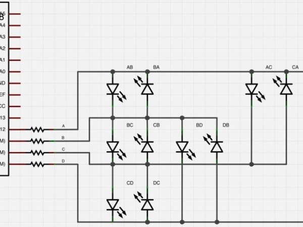
Step #1: Schematic
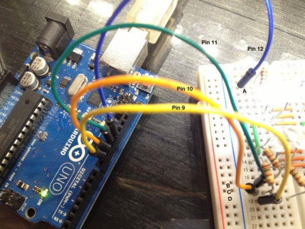
- I’ve labeled the schematic to match the photos used to build the project. The Arduino pins 9, 10, 11 and 12 are used to control the LEDs and I’ve labeled them from 12 down to 9 as A, B, C and D.
- The second image shows the current path when pin A is HIGH, B is LOW and C and D are set to INPUT.
- The third image shows the current path when pin B is HIGH, A is LOW and C and D are set to INPUT.
- When I map out Charlieplexing LEDs, I use the A/B/C labeling to make it easier to keep track of what’s going on. For instance, LED “AB” is the LED that’s lit when current goes from A to B. LED “DA” is the LED that’s lit when D is HIGH, A is LOW and the other pins are set as INPUT.
Step #2: Breadboard Setup – Jumpers/Wiring
- The little breadboard I’m using has only 5 holes in each row on each side of the board. I jumpered the two sides together with the shorter (orange) jumper wires.
- I had to extend each row (A, B, C) down to another set of rows to give us more holes to plug LEDs into. I used longer (green) jumper wires to do this.
- The second set of rows has a row for pin D.
Step #3: Plug In LEDs – AB, BA, BC, CB, CA and AC
- Pairs of LEDs will go into the same rows together, but their leads will be opposite of each other.
- For the first 3 pair, I’ll label them and point out what’s positive and what’s negative on the LEDs. The next step won’t have the polarity marked. However, you’ll still have the LED labels and you’ll know by that (i.e., “DA”) which way it goes in and to what pins it should be connected.
LED
For more detail: Charlieplexing LEDs with an Arduino
- How many LEDs can be controlled with 4 pins?
You can control 12 LEDs using the formula N pins multiplied by N pins minus 1. - Can you light more than one LED at a time with this method?
Yes, you can light multiple LEDs by scanning them on and off very quickly. - Why is Charlieplexing less useful for two LEDs?
With only two pins, it is simpler to connect each LED directly to a pin and ground rather than using Charlieplexing. - What limits the total current in an ATmega328?
The grand total of current from Vcc to GND in an ATmega328 is capped at 200 mA. - How do you identify which LED lights up between two pins?
An LED labeled AB lights when current flows from A to B, meaning A is HIGH and B is LOW. - What pin states are required for unlit connections?
Pins not involved in lighting a specific LED should be set to INPUT mode. - How are LEDs arranged on the breadboard rows?
Pairs of LEDs go into the same rows together but with opposite polarity leads. - Does the ATmega328 source enough current for individual LEDs?
Yes, the pins can source upwards of 40 mA, though the project limits usage to roughly 20 mA per pin.