I love Ardunio. I love the things that people make with them and I love to make my own. Last August I published an Instructable on how to make your own postage stamp sized Arduino compatible. This Instructable will show you how to to make a rugged, versatile Ardunio compatible with basic components on board. It will be more suitable for deployment in the real world than a bread board attached to a development board. This video is from the Kickstarter, but you can totally make your own.
This open source hardware project is licensed Creative Commons CC-BY. Part of my philosophy of open source hardware means I don’t consider a design released without detailed build instructions. Instructables is my favorite place to release those Instructions.
Why don’t I just stick with an Arduino, some shields, a breadboard and components like people usually do?
Take a look through some Arduino projects with LCDs. A lot of those projects are still on breadboards. They do amazing things, but they have some challenges.
- Delicate connections may not survive long in the real world
- Hard to move
- Hard to duplicate
- Development board is now trapped in the project
- Your friend wants one, but you don’t want to give them something that needs fixing all the time
- Your Mom looks at it wrong and it breaks. (True story. [Hi Mom!])
How can I solve those problems?
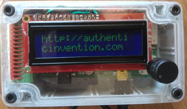
Follow along and you can make your own Arduino Compatible in an enclosure with on board screen, controls, speaker, USB and some other goodies.
Cool, I want to make one! How hard will this be?
This is a somewhat challenging project that involves surface mount soldering. If you ever built an Arduino from components on a bread board or made your own circuit board you probably have all the skills you need. These instructions include all the parts lists and design files you need to create an Arduino compatible board.
I still want one but I’m not sure I have the time or skills.
We have a Kickstarter running until Monday July 2nd, 2012.
Step 1: Gather tools and software
Skills
- Basic familiarity with Arduino environment and programming.
- Enough electrical engineering know-how to read instructions and put together circuits.
- Basic Soldering skills and a willingness to and ability to work with surface mount soldering.
Physical Tools
- Electric skillet or griddle
- Good ventilation
- Fine tweezers that are not even a little magnetized. Plastic is OK.
- Big tweezers/hemostat or some other way of moving circuit boards that can take 400 degrees F. Magetized is OK, clearly plastic is not.
- Magnifying glass and/or loupe.
- Solder paste
- Syringe or heavy duty zip top bag with a needle hole in the corner for applying paste
- Sewing needle
- Soldering Iron (Adjustable if at all possible)
- Fine solder wick
- Sharp knife (hobby knife)
- Wire strippers
- Multi Meter
- Any arduino compatible or ISP known to work with Atmega chips. These instructions assume an Arduino loaded with ArduinoISP
- Some male to female breadboard jumpers.
- A PC, these instructions assume windows. Linux will also work for sure.
- (Optional) Helping hands or a vice for holding the PCB while you solder it.
Software
- WinAvr (Optional)
- Arduino IDE, 1.0 was used for these instructions.
Step 2: Get the circuit boards
You may choose to DIY (Here is how I did it for my prototypes) or send it to a “fab house.” Fab services require design files in a compatible format. “Gerber” is a common format just about every board manufacturing service accepts.
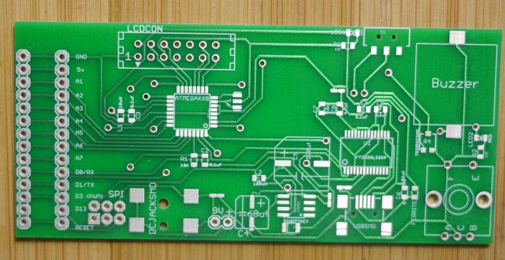
Here are the Gerber files. Alternatively, You can also get the Eagle Files from GitHub and make your own Gerbers (or whatever). You can send the Gerbers to a fab house like BatchPCB or www.sunstone.com. I have used both. Sunstone’s prototype service costs about twice as much and you will have boards in half the time. The quality of the Sunstone boards is great. The price at Sunstone is the same for one or two boards so go ahead and get two and consider getting two sets of electronics.
The first and third photos are boards from Sunstone and the second photo is one I did at home with atoner transfer method.
Step 3: Gather Components
Electronics
Here are the parts you need and the digeykey part numbers. For items that don’t have a minimum of 10, I recomend you get at least 2 and possibly more. If you have 2 good boards, you can make two Ardunio Compatibles. The small parts are really, really easy to lose so having extras is great. Consider ordering extras of the cheaper components. Be careful with them when you open the packages. You can get all the parts from Digikey. Try to salvage some 14 conductor ribbon cable from an old computer if you can, unless you need 5 feet of the stuff.
Some parts are only available in quantities greater than you need for this project. You’ll have to buy extras. At the time of this writing these parts will cost about $35 US.
| Quant | Digikey PN | Description |
| 1 | 668-1110-1-ND | BUZZER PIEZO 5.0V 16MM SMD |
| 1 | 754-1131-1-ND | LED 2X1.2MM 568NM GN WTR CLR SMD |
| 1 | ED2992CT-ND | CONN USB MINI B R/A SMD |
| 1 | WM26814-ND | CONN HDR DUAL 14POS .100 SRT AU |
| 1 | OR914-ND | CONN SOCKET 16POS FLAT CABLE IDC |
| 1 | MC16G-5-ND | CABLE 16 COND 5FT FLAT GRAY* |
| 1 | CP-002APJCT-ND | CONN POWER JACK 2.1X5.5MM SMD |
| 1 | LM2594M-5.0-ND | IC REG SIMPLE SWITCHER 8-SOIC |
| 1 | 565-2476-1-ND | CAP ALUM 68UF 35V 20% SMD |
| 1 | 493-4380-1-ND | CAP ALUM 120UF 25V 20% SMD |
| 1 | 445-1369-1-ND | CAP CER 4.7UF 16V Y5V 0805 |
| 1 | 641-1325-1-ND | DIODE SCHOTTKY 1A 40V MINI-SMA |
| 1 | 475-1278-1-ND | LED CHIPLED 633NM RED 0805 SMD |
| 1 | 401-2012-1-ND | SWITCH SLIDE SPDT 12V 100MA GW |
| 1 | 987-1194-ND | ENCODER 12MM ROTARY SW TOP ADJ |
| 1 | ATMEGA328-AU | IC MCU AVR 32K FLASH 32TQFP |
| 1 | 587-2048-1-ND | INDUCTOR 100UH 0805 |
| 1 | 490-1198-1-ND | CER RESONATOR 16.0MHZ SMD |
| 1 | RHM10.0KAECT-ND | RES 10.0K OHM 1/4W 1% 0805 SMD |
| 5 | 478-1395-1-ND | CAP CER 0.1UF 50V 10% X7R 0805* |
| 1 | 240-2399-1-ND | FERRITE 500MA 600 OHM 0805 SMD |
| 1 | 478-1383-1-ND | CAP CER 10000PF 50V 10% X7R 0805 |
| 1 | 67-1781-ND | LCD MODULE 16X2 CHARACTER |
| 1 | 490-4611-1-ND | TRIMMER 10K OHM 0.1W SMD |
| 1 | 768-1007-1-ND | IC USB FS SERIAL UART 28-SSOP |
| 2 | RHM220AECT-ND | RES 220 OHM 1/4W 1% 0805 SMD |
Connectors.
The 11 I/O pins along the left side will need some headers. You have some choices.
- Pin Headers You’ll need at least 6 of these no matter what for the SPI header. Get 14 more if this is how you want to connect to your off board electronics. 90 degree headers are what I used in the video.
- Screwless terminals are in some of the photos and are a great choice. Get a pack of 6’s and a pack of 2’s and you can pry them apart and make a 14. The holes are spaced for these.
- Basic familiarity with Arduino environment and programming.
- Enough electrical engineering know-how to read instructions and put together circuits.
- Basic Soldering skills and a willingness to and ability to work with surface mount soldering.
Physical Tools
- Electric skillet or griddle
- Good ventilation
- Fine tweezers that are not even a little magnetized. Plastic is OK.
- Big tweezers/hemostat or some other way of moving circuit boards that can take 400 degrees F. Magetized is OK, clearly plastic is not.
- Magnifying glass and/or loupe.
- Solder paste
- Syringe or heavy duty zip top bag with a needle hole in the corner for applying paste
- Sewing needle
- Soldering Iron (Adjustable if at all possible)
- Fine solder wick
- Sharp knife (hobby knife)
- Wire strippers
- Multi Meter
- Any arduino compatible or ISP known to work with Atmega chips. These instructions assume an Arduino loaded with ArduinoISP
- Some male to female breadboard jumpers.
- A PC, these instructions assume windows. Linux will also work for sure.
- (Optional) Helping hands or a vice for holding the PCB while you solder it.
Software
- WinAvr (Optional)
- Arduino IDE, 1.0 was used for these instructions.
For more detail: Make your own custom Arduino compatible