In the spirit of Earth Day, I have created a revolutionary new energy-saving lighting solution that is only ever on when your eyes are open. This is remarkably more efficient than normal lighting that remains on, even when your eyes are shut. Using my device, you get light when you need it, and darkness when you don’t. This is not only beneficial to you and your energy bill, but great for mother Earth.
This device was made as part of my ongoing effort to use less energy, reduce my footprint, and prevent climate change. I foresee similar technologies being implemented in televisions, computers, and electric cars. I am confident that future generations will thank me for this innovation.
Step 1: Go get stuff
(x1) 3″ x 2″ x 1″ project enclosure
(x3) AC power sockets
(x1) SmartFan AC-VX fan controller
(x1) Arduino
(x1) Arduino project board
(x2) 1/4″ stereo sockets
(x1) 4-pin female header socket
(x2) 9V battery connectors
(x2) 9V battery clips
(x2) 9V batteries
(x1) EMG sensor board
(x1) set of electrode cables
(x3) adhesive electrodes
(x1) cable stress gland
(x1) European terminal strip
(x1) AC lamp cord (with plug)
(x1) 1/4″ male-to-male stereo cable
(x10) 6-32 x 1″ nuts and bolts
(x8) 4-40 x 1″ nuts and bolts
(x2) 4-40 x 1/4″ nuts and bolts
(x1) spool of 14AWG stranded wire
(x1) acrylic front panel (from attached template)
(x1) acrylic mounting base (from attached template)
 energyLight.eps269 KB
 EnergySaverbaseplate.eps318 KB
Step 2: Wire the sockets
Connect together the left side of all of the sockets with 14 gauge wire.
Repeat the process for the right side.
Be careful to keep the two sides separate.
Step 3: Mount
Mount the sockets into the acrylic panel using 6-32 nuts and bolts.
Step 4: Project board
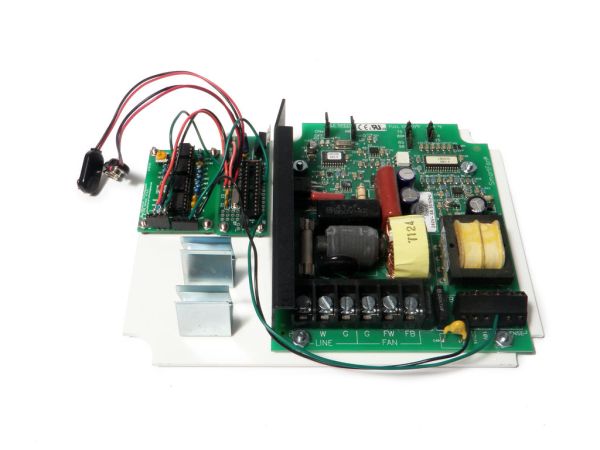
Build the Arduino project board as seen here (minus the 9V battery clip). Alternately, you can check out the Hackduino project for something similar.
Wire two 9V battery clips in series to create a +/-9V power supply.
Looking at the wires from the battery clips, connect the single red wire to the +V input on the Arduino project board. Next, connect the red and black wire junction to the ground input on the Arduino project board.
Solder a 6″ green wire to one of the outer pins of the female socket. Solder a 6″ black wire to the pin next to the green wire, and a 6″ wire to the pin next to the black wire.
Solder the other end of the socket’s green wire in line with the single black wire of the 9V socket supply. Solder the black wire in line with the center point of the two 9V sockets. Lastly, solder the red wire in line with the singular red wire (that is also connected to the voltage input on the project board)
Connect 6″ green wires to pins D9 and A1. Also, connect two extra 6″ black wires to ground.
Step 5: Mount
Using nuts and bolts of appropriate size, mount the fan controller, Arduino project board, EMG board, and two 9V battery clips to the acrylic mounting base.
Step 6: Drill
Drill a 1/8″ hole in the center of one of the smaller sides of the 8″ x 6″ x 3″ project enclosure (the 6″ x 3″ side). Repeat this on the other side.
Widen one of the holes to 3/8″ and the other hole to 7/32″
[box color=”#985D00″ bg=”#FFF8CB” font=”verdana” fontsize=”14 ” radius=”20 ” border=”#985D12″ float=”right” head=”Major Components in Project” headbg=”#FFEB70″ headcolor=”#985D00″](x1) 8″ x 6″ x 3″ project enclosure
(x1) 3″ x 2″ x 1″ project enclosure
(x3) AC power sockets
(x1) SmartFan AC-VX fan controller
(x1) Arduino
(x1) Arduino project board
(x2) 1/4″ stereo sockets
(x1) 4-pin female header socket
(x2) 9V battery connectors
(x2) 9V battery clips
(x2) 9V batteries
(x1) EMG sensor board
(x1) set of electrode cables
(x3) adhesive electrodes
(x1) cable stress gland
(x1) European terminal strip[/box]
For more detail: Energy-Saving Light using an Arduino


