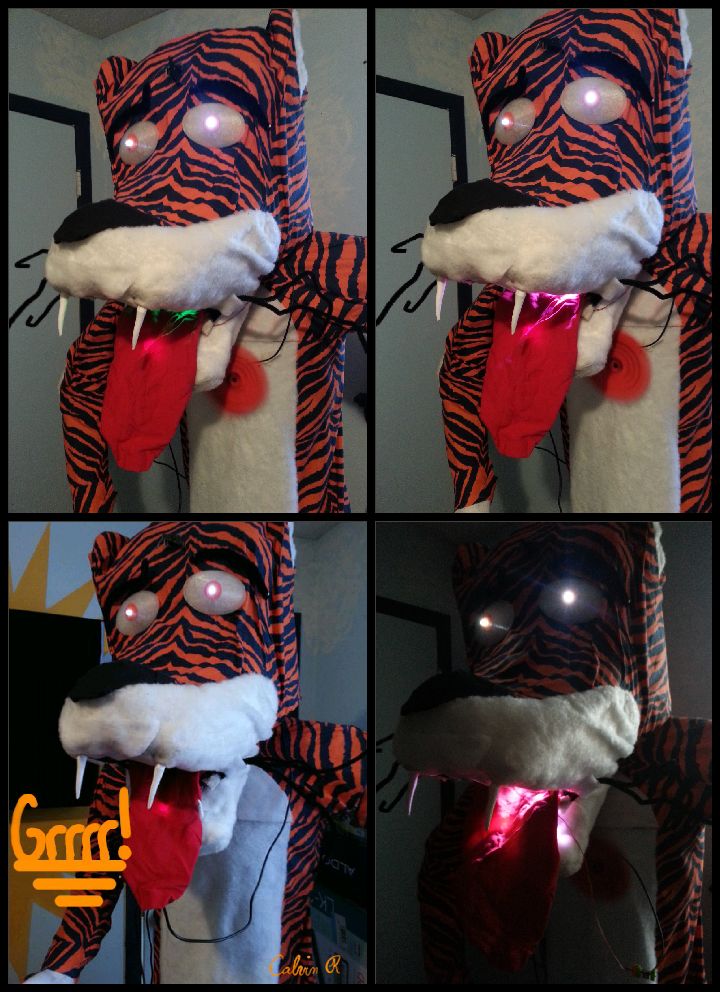
Say Hello to littleBitty Joe! Joe is my school’s mascot! Speak to Joe and watch his eyebrows lift, whiskers vibrate, eyes illuminate, heart spin and hear him ROAR! Not only does his roaring affect work with our project, but it can definitely work with your littleBits project too! Your project could talk, scream, or say just about anything!
I am deeply passionate for helping others and I am currently volunteering at a local school to assist their robotics club, STEAM Club, and to also serve as a mentor. Ultimately, I want to teach urban & “at-risk” students the art of Engineering by using Art & Music to gain their interest within the subject! After meeting Ayah Bdeir and using littleBits, I recognized the teaching potential littleBits has while students engage in fun & interactive activities that sparks their creativity. I am currently in the planning process of creating my own littleBits workshop to schools & community centers within the community I live now. I plan to provide them an inspiring education in engineering with the use of what they are normally engaged in, art & music. “Tell me and I forget. Teach me and I remember. Involve me and I learn.” — Benjamin Franklin. Students should be deeply involved in what we learn.
Parts for Head:
LittleBits: Power Bit + Sound trigger + Branch + Vibration motor (2) + Wire (3) + Fan + Servo + Long LED (2) + Bright LED. 330 ohm Resistor (1), 4.7 K ohm Resistor (1), Adafruit Audio Wave Shield (1), Arduino Jumper Wires (red, yellow, black), Arduino Power Supply (1), Arduino Uno, Black fabric, Cardboard, Chicken Wire (3 ft.) , Electrical tape , Fish wire or thread , Flour , Masking, Tape, Newspaper, Photodiode, Pipe Cleaner (10), Power adapter & Cable for Arduino, Red fabric, Scotch tape , Sewing pins, Solder, Speakers with Auxiliary Cord, Styrofoam mannequin head, Tiger Striped fabric, Water, White “Fuzzy” fabric, Zip ties (10).
Parts for body:
2 to 3 rolls of duct tape, one extra large trash bag, plastic wrap, (2) 1-1/2 in x 10ft. PVC Pipe, (4) T-Connectors, (4) 90-degree elbow connectors, (2) 45-degree connectors, old shoes, styrofoam, needle & thread, sewing machine
Tools:
Mixing bowl, spoon, Computer with Arduino IDE, Dry Towel, Hot Glue Gun, MakerBot Replicator 2, Scissors, Soldering Iron, Hacksaw, Filing Tool, ABS Solvent Cement, black spray paint, white spray paint, Exacto knife, electric knife, a black Sharpie, workbench, measuring tape & an extension cord.
Roaring Effect
Additionally, the roaring affect can be used with other littleBits projects, so feel free to use it! Skip to steps 7, 8, & 9. Can’t wait to see what cool projects you invent with littleBits!
Step 1: LittleBits Circuit
Let’s begin with building the circuit: power + sound trigger + branch. Add (1) vibration motor to each arm of the branch, which will be used for whiskers. On one of the two vibration motors, add a wire bit and fan. The fan will be used for the heart. Connect (2) wire bits and add them to the head of the branch. Attach the second wire bit to the second half of the circuit: long LED + long LED + servo + bright LED. For now, the bright LED bit can be placed to the side, as it will be used later through the tutorial. Lastly, set the servo to swing-mode.
Step 2: Mount the littleBits to cardboard
Secondly, let’s mount the circuit to two separate rectangular pieces of cardboard. The dimensions of each piece of the cardboard should be close to 2” x 4”. It is best to tape each bit link together with scotch tape to avoid disconnection. Use two strips of scotch tape to mount the first half of the circuit to the cardboard, excluding the wire bits. Apply the same process to the second half of the circuit, excluding the wire bit; the wire bits should be free of mount. Lastly, test the circuit to ensure it’s functionality.
Step 3: 3-D Printing
Before we begin to build the head of the tiger, let’s 3-D print a few cool items. We used the MakerBot Replicator 2 to print the eyeballs, teeth, and claws. Download the .thing files and upload them to a MakerBot. This process may take a few hours, so check the status of the items frequently. If you don’t have access to a 3-D printer, ping pong balls can be used for eyeballs and the teeth can be made from white colored play-doe. Once the teeth and claws are printed, spray paint the claws black and the teeth white.
Step 4: Head Assembly
Now, let’s begin the assembly of the tiger’s head. Use the styrofoam mannequin head as the support of the frame. Starting from the back of the mannequin, wrap the chicken wire around the head to form a one layer frame; cut the excess chicken wire using the wire clippers and tape the frame together with masking tape. The chicken wire should circle around the mannequin with at least 2 inches of space between the mannequin and the frame on each of the head. Since the height of the chicken wire is over two feet, you can cut and bend the wire to form a dome shape as top of the head. First, cut the chicken wire around 6″ down the back of the head, fold the back sides inwards towards the middle, cut the sides, and overlap the front of the head backwards towards the middle of the mannequin. Now, use 8 strips of masking tape to tape to secure the wire down. Each strip should intersect at the center of the dome and continue it’s path to the bottom of the frame. The main section is complete.
Step 5: Assembly of nose & mouth sections
Next, is the nose and mouth section. Cut a length of 22″ of chicken wire and fold it into an arch. Curve 2″ of the bottom of both sides of the arch towards the inside of the arch at a 45 degree angle. Tape this section of the mouth as the top portion of the mouth to the main section of the head. Complete this process for the bottom of the mouth, but tape it to the main section at a 315 degree angle instead. Tape four strips of masking tape to the top portion of the mouth, starting from the main section of the head to the opening of the mouth. Complete the same process for the lower section of the mouth. If you don’t like the shape of the head, add folded pages of newspaper to create the form you want and use masking tape to secure the newspaper. It is recommended to add more newspaper to the joint of the main section and the top of the mouth. Additionally, on the top of the dome.
Step 6: Paper Mache Skin
We have made it to the sticky step of the tutorial; it’s time to form the skin of the tiger! Ensure that there is enough tape on the head for the newspaper & paste to stick to. First, we need to create a paper mache paste with newspaper + flour + water + mixing bowl + spoon. Mix 1 part water with 1 part flour in the mixing bowl and tear 3″ x 7″ strips of newspaper; also keep some bigger sheets as well. Work on a dry cloth inside or work outside, this will be a very sticky step. Dip a newspaper strip in the paste and start to shape the head from the top of the dome. Cover one layer of newspaper, one strip at a time on the entire head. Be sure to shape the section where the main section of the head and the mouth section joins. Allow the head to dry. Once dried, add another layer to the head and allow the head to dry again. On the third layer, fold larger strips of newspaper together to form ears. Allow to dry. Complete this layer process two more times. This step may take a few hours so feel free to rest. Once the head is completely dry, move to the next step.
Step 7: Voltage Divider Circuit
In this step we will design a voltage divider circuit: bright LED + 4.7k ohm resistor + 330 ohm resistor + photodiode + jumper wires (red, black, yellow) + electrical tape + solder + soldering iron. First, twist the leads of the two resistors together and twist a black jumper wire to the second lead of the 330 ohm resistor. Next, twist a yellow jumper wire to the other lead of the 4.7k resistor (both leads should face the same direction). Twist the combined leads of the yellow wire and the 4.7k resistor to one of the photodiode leads. Next, twist a red wire to the second lead of the photodiode. After all of the necessary leads are twisted, pull out your soldering iron & start soldering! Solder each of the twisted leads together. After each lead is soldered, secure the soldered joints with electrical tape. In the next step, you will need: bright LED + electrical tape + photodiode. Take the photodiode and place the face of it onto the LED of the bright LED; ensure that it is placed directly on the LED. Lastly, use electrical tape to secure the photodiode in place.
Step 8: Program the arduino & waveshield
Let’s start programming. In this step, you’ll need: computer with Arduino Uno IDE software + Arduino Uno + Adafruit Audio wave shield + SD Card + the programming cable. Place the wave shield on top of the arduino and load the arduino program on the computer. Download the arduino code file and download it to the IDE programmer. Make sure the programmer is connected to the correct communications port. Upload the code to the arduino and waveshield. Once the code is uploaded, remove the arduino from the computer. Now, download the tiger-roar2.wav file to the SD card. You can use this process to upload different sounds and audio to the SD card for other projects. If you want to use specific audio saved in different formats ( .mp3 .mp4 etc.), be sure to convert these files to the .wav format. Download and extract the file to the SD card. You have officially programmed an arduino and wave shield!
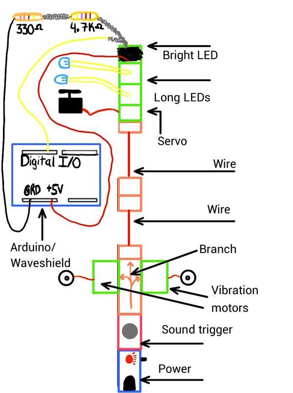
Step 9: Combine both circuits
We will now combine the littlebits circuit with the arduino circuit. In this step you will need: voltage divider circuit + Arduino & Adafruit Audio wave shield + Solder + Soldering Iron. We will solder the jumper wire leads to the 5 Volt pin (red wire), GND pin (black wire), and the digital input/output pin 8 (yellow wire). Ensure that the face of the photodiode is still in direct contact with the LED of the bright LED bit; this is the main link between the littlebits and arduino. The bright light from the bright LED bit lowers the resistance of the photodiode, which allows voltage flow through the signal wire (yellow) to trigger the arduino & waveshield. More light activates the circuit, less light deactivates the circuit. To test the combined circuit, connect the arduino to a power supply, connect the wave shield to the speakers, power up the littleBits, and snap your finger in front of the sound trigger to activate the arduino. Immediately after the snap, there should be a loud “roar”. If nothing happened, check the volume level of the wave shield, ensure that the face of the photodiode is in direct contact with the LED, check for cold solder joints in the voltage divider circuit, ensure the file on the SD Card is in a .wav format, or reprogram the arduino. Additionally, you may need to add electrical tape to the metal casing of the A/B USB port on the arduino; this may cause a shortage in the waveshield.
Note: Use a wall adapter instead of a 9 V battery, the batteries will drain rather quickly.
For more detail: LittleBitty Joe using arduino