Using this method, I’ll show you how you can access 5 (or even more) inputs through 1 Arduino pin. These buttons will only be read correctly if only one is pushed at any time though.
As we go through it I’ll explain whatever background info you need to know, so as long as you can blink a button, read a switch and read an analog input, you’ll be fine. If you can’t do any of these, I’ll point you in the right direction in the relevant steps as well.
Step 1: Parts List
This is pretty simple:
1 x Arduino (Obviously)
1 x 100K Resistor (Brown Black Yellow)
1 x 1K Resistor (Brown Black Red)
1 x 10K Resistor (Brown Black Orange)
1 x 33K Resistor (Orange Orange Orange)
1 x 68K Resistor (Blue Gray Orange)
4 x Push button switches
Some wires to connect it all
You can use any push buttons you might have lying around, and the resistor values are not critical. More on this later.Step 2: The theory – How buttons are normally read.
Lets first look at how you would normally read a button. In its simplest form, you would connect your button like the circuit shown.
As you can see, you need 1 Input pin and 1 resistor per button, and then you can check the state in your Arduino sketch using thi
I’m not showing all the setup etc… Obviously you need to declare everything and set the pin as an input, etc. You can see the full example on the Arduino website.
This is fine if you are only using 1 or 2 buttons, but what if you need 10? That leaves very little IO pins for anything else you might want to do.
So how do you put multiple buttons on one pin?
You cheat! The secret to this is using an analog input pin, not digital.
You can read about how the analog input works by going through this Arduino tutorial. Essentially, what you need to know though is that when there is 0V on the analog pin, analogRead() returns a value of 0 and if there is 5V, analogRead will return a value of 1023. For any voltage between 0V and 5V, analogRead will return a number proportional to the voltage.
We can’t actually change the voltage that is supplied to the pin (Not easily at any rate, and I’m lazy, so easy is important), but if you remember from Ohms law, V=IR. The current (I) is fixed, which means that we just need to add a resistor between the supply voltage and the analog pin to change the voltage.
For those of you that were getting excited about all the maths that’s necessary to calculate the voltages, I’m going to have to disappoint you… I’m lazy, so I don’t need maths.
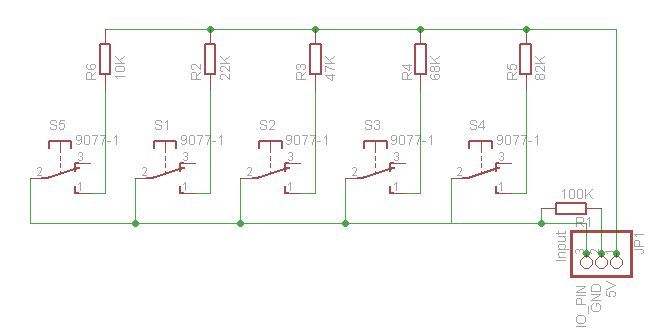
Let’s get a bit more practical, and I’ll show you why we don’t care about the maths. We know that the analog pin reads voltages and we know that we can change those voltages by adding a resistor between it and the supply voltage. We also know that we’ve gone this far because we want to be able to read switches, so we should probably toss some switches in too.
Now, for those that are interested, To design this, you start with what you know. I know how to connect a single switch to a single input. I wanted 5 buttons, so I duplicated it 5 times. I then simplified it by having a single pull down resister connected to all the buttons, and then simply put resistors between the buttons and the supply voltage and tied all the inputs together.
If you connect each button to the supply voltage through a different value resistor, depending on which button is pushed, the value returned by analogRead would be different, and you can use a bunch of if statements to see which button was pressed. The reason we don’t need maths is because we just connect it all up, push the buttons and print the returned values to the serial port.
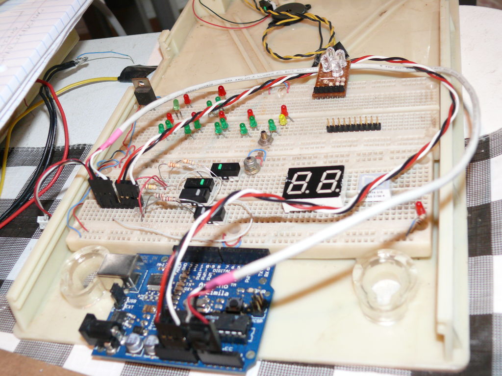
Step 4: At last we can breadboard it.
Using the previous circuit, build it on a breadboard. I’ll show you how I did it, but this is very dependent on which buttons you use, so you’ll need to use your imagination. I used micro buttons from old computer mice. I also only had 4 buttons (that worked properly at any rate), so I decided to only do 4 buttons, but the code is set up to handle a 5th button.
Once the circuit is built, you can hook up the GND and 5V to the Arduino, and connect the buttons to analog pin 0 (You can change it, just remember to change it in the sketch).
Remember that I said we don’t need the maths? I prefer trial and error. For your resistor values, you should pick values that are fairly evenly spread between an arbitrary lower and higher range. I found that values spread between about 1K and 100K work best. For my resistors, I happened to have 1K, 10K, 33K and 68K lying around, so I used those. If I had a fifth button, i would add a 47K resistor between 33K and 68K.
After I built it, I realize now that the 1K resistor is probably not needed. One of your buttons could be connected directly to 5V, so you need one resistor less than buttons (and the one pull down resistor shared by all the buttons). If one of your buttons is connected to 5V it should always return a value of 1023. So if you want to save a couple of cents, leave out the resistor on button 1.
Step 5: Testing it
Download the attached sketch and upload it to your Arduino. Once it is uploaded, open the serial monitor as well. to test it, watch the serial monitor and then hold down button 1. You will see that the values returned will fluctuate for a bit before settling down in a small band of numbers. Write down the biggest and smallest numbers.
Using the 1K resistor with my button, I got values ranging between 988 and 1011.
After repeating this for all the buttons, I got the following values:
Using the 1K resistor with my button, I got values ranging between 988 and 1011.
Using the 10K resistor with my button, I got values ranging between 910 and 929.
Using the 33K resistor with my button, I got values ranging between 767 and 768.
Using the 68K resistor with my button, I got values ranging between 400 and 609.
The first thing that is clear is that the range is bigger for some buttons. I retested several times with consistent results. I actually replaced the second button because I was getting all kinds of results. I was getting numbers ranging from about 510 all the way through 910, so if you get a huge range of numbers, try a different button.
Once you have these values, you can create a sketch that will read the state of a specific button.
Step 6: Coding it.
To code it, I simply took the debounced button example and modified that to set a state based on which button was pressed rather than just a simple HIGH or LOW state.
You can download the attached sketch. It is actually quite simple. The first section sets up all the variables and constants we’ll use.
[box color=”#985D00″ bg=”#FFF8CB” font=”verdana” fontsize=”14 ” radius=”20 ” border=”#985D12″ float=”right” head=”Major Components in Project” headbg=”#FFEB70″ headcolor=”#985D00″]
critical
Obviously
proportional
previous circuit[/box]
For more detail: How to access 5 buttons through 1 Arduino input