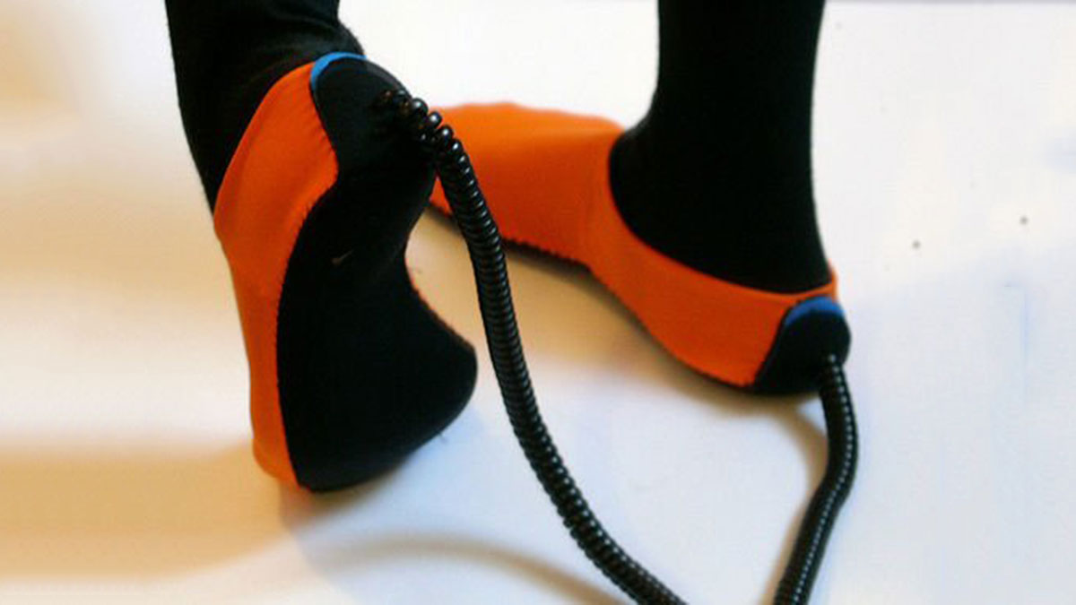
These slippers have 4 analog pressure sensors embedded. They can be used to feed Up, Down, Left and Right values into your computer replacing your mouse, joystick…
Visit the JoySlippers website >> http://www.joyslippers.plusea.at/
This Instructable improves upon the previous version http://www.instructables.com/id/Joy-Slippers/.
It will show you how to make a pair of Joy Slippers, connect them to an Arduino physical computing platform and run a Processing application that will allow you to draw with your feet, as seen in the following video.
The resistance range of the pressure sensors depends a lot on the initial pressure. Ideally you have above 2M ohm resistance between both contacts when the sensor is lying flat. But this can vary, depending on how the sensor is sewn and how big the overlap of the adjacent conductive surfaces are. This is why i choose to sew the contacts as diagonal stitches of conductive thread – to minimize the overlap of conductive surface. With the pressure sensors inside the JoySlippers, the initial pressure from simply wearing them, brings the resistance down to about 2K ohm and then when fully pressured by standing on the foot it goes down to about 200 ohm.
The next step (for me) is to find better applications for the Joy Slippers. The videos of the drawing application show that certain motions create certain patterns, meaning that they can be tracked.
I’m experimenting with some ideas for applications that make use of this and would appreciate any feedback, comments, ideas…
For more videos visit the YouTube Joy Slippers playlist
For more pictures visit the Flickr Joy Slipperes set
http://flickr.com/photos/64586501@N00/sets/72157603880355045/
Materials
The materials that you will need are simple, but it’s probably not all stuff you have lying around your house. It comes cheap if you plan on using the materials for future projects, especially if you are interested in wearable technology or soft circuits.
So, how does it work?
The layering of conductive and ex-static in the slipper’s soles creates very very simple variable resistors that are pressure sensitive. The layer of ex-static plastic between your conductive thread patches allows for more current to pass through, the harder you push the conductive layers together. I’m not 100% sure why it works, but it does, and it is amazingly stable. So by shifting your weight from left to right and tiptoe to heel you can generate pretty much every direction.
For up-to-date information visit the project website >>
http://www.plusea.at/projects.php?cat=1&work=14
Step 1: Materials and tools
MATERIALS for the Joy Slippers:
– Conductive thread – 117/17 2ply (17USD from www.sparkfun.com)
– Ex-static – plastic from the black bags used to package sensitive electronic components
– 6 mm thick neoprene with jersey on both sides (ask at a local surf shop for leftovers, or if you live in Europe and plan to use neoprene for other things, get a sheet from www.sedochemicals.com)
– Stretchy fabric (you can also use a pair of old socks if you don’t feel like sewing so much)
– Regular thread
– Perfboard with copper line pattern (7×3 holes 6.25USD from www.allelectronics.com)
– 50ft Spiral telephone wire (1.99USD at 99cent store)
MATERIALS to make Arduino connection:
– 4 x 10K Ohm resistor
– Perfboard with copper line pattern (6×6 holes)
– 15cm of rainbow wire with 6 cables
– 2 telephone jack outlets (5 for 1.50USD at 99cent store)
– Tupperware box or similar
– Solder
– Superglue
– Arduino USB Board (35USD from www.sparkfun.com)
– USB cable (4USD from www.sparkfun.com)
– Laptop or computer (hopefully you have one, or can borrow one)
– Processing installed on your computer (download free from www.processing.org)
– Arduino software installed on your computer (download free from www.arduino.cc)
TOOLS you will need:
– Sewing needle
– Scissors
– Cutter
– Ruler
– Pen and paper or cardboard
– Your feet
– Multimeter for checking your work
– Soldering iron
– Third hand
– Pliers or some kind of wire cutter
(- Bread-board)
SKILLS required:
You will need to be able to solder. Soldering is not hard and there is a nice Instructable right here: http://www.instructables.com/id/How-to-solder/
You will need to know how to use the Arduino software environment, in order to upload following code to your microcontroller. It will read the first 4 analog inputs and receive them via USB.
www.plusea.at/downloads/_080201_Read_4AnalogIN.zip
Following Processing application will read the incoming values from the Arduino’s inputs and use the information to draw a line.
Input will be read as follows:
Analog INPUT [0] = Right foot TOES
Analog INPUT [1] = Right foot HEEL
Analog INPUT [2] = Left foot TOES
Analog INPUT [3] = Left foot HEEL
_080209_JoySlippers_etchAsketch.zip www.plusea.at/downloads/ _080209_JoySlippers_etchAsketch.zip
For more detail: Joy Slippers Version 2 using Arduino