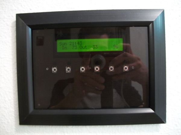
Build a nice looking LCD display with buttons for mounting on the wall.
Key Features:
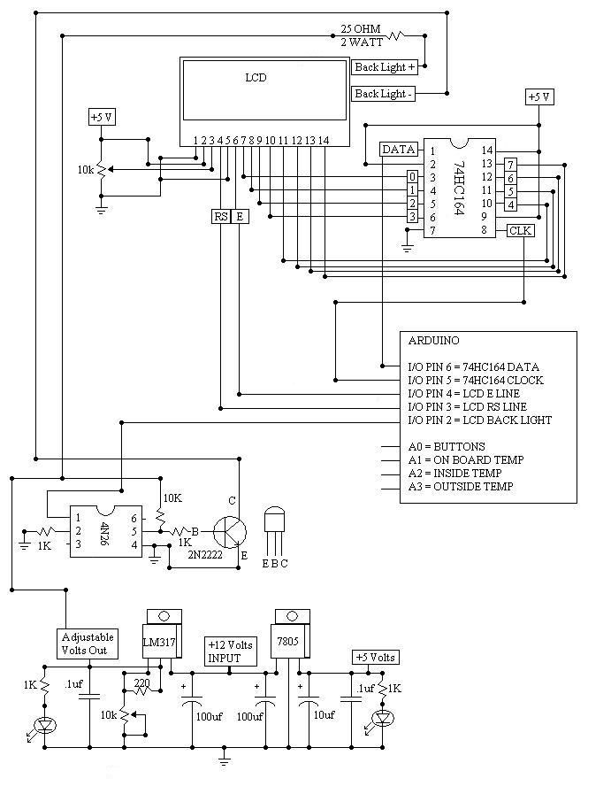
2 line by 24 character LCD display controlled with 4 I/O’s (74HC164).
Back light control of LCD.
6 Buttons connected to 1 analog pin.
LM335 and LM334Z temp sensors.
Adjustable temperature offset.
Simple software clock.
Wall mounted in a picture frame.
Step 1:
Many times I have gone to a lot of trouble to build a project and when it comes time to have a display somewhere the stuff I put on the wall is less than appreciated by those around me.
Sometimes even becoming such a point of curiosity for my youngest that it ends badly.
One day while looking at a shadow box picture frame I thought… I bet I could stuff some electronics in that. This is what I came up with. Its not in a shadow box frame but for what I have planned this works a little better.
I started by taking a look at the size of the general purpose proto board and the LCD. I knew the frame would have to be at least large enough for them. I also did not want to have any screws sticking out ( or even screw heads ) when this was finished.
Parts Lists.
Picture Frame:
1- 5X7 picture frame (dollar store).
4- Screws for the LCD
6- Buttons ( Normally open)
2- General purpose proto boards.
8- #6-32 Brass Machine Nuts.
4- #6-32 x 3 / 4 Brass Machine Screws.
1- 3 / 8 x 12 inch Smoked Acrylic sheet.
1- 8 x 10 x .093 Lexan sheet.
8- Sheet rock screws and anchors ( Mounting display ).
3- Packages Micro rare earth magnets.
4- #6 x 3 / 4 Phillips Pan Head Screws.
Electronics parts:
1- Arduino Uno
1- 24 character 2 line LCD.
1- 7805 voltage regulator.
1- LM317 adjustable voltage regulator.
1- 74HC164 serial in parallel out shift register.
1- 4N26 optical isolator.
1- 2N2222
2- 100uf capacitors
1- 10uf capacitor
3- .1uf capacitors (noise reduction)
2- infrared leds
6- Normally open buttons
14- 10K resistors.
4- 1K resistors
1- 220 Ohm resistor
2- 10K potentiometes
1- 25 Ohm resistor (2 Watt plus).
Temp sensors:
LM335 – each
2- 1K resistors
LM334Z – each
1- 220 Ohm resistor
1- 10K resistor
Jumper wires.
Tools:
Hand held drill.
Hand held cutting tool ( Dremel ).
Pack Number 409 Cutting Wheels ( Dremel ).
Acrylic Cutting Knife.
Screw Driver.
Dust Mask.
C Clamps.
Scrap Piece of wood.
Paper towels.
Solder Iron.
Solder.
Glue.
Round File.
Flat File.
Assorted Drill Bits.
150 Grit Sand Paper.
Square.
Metal straight edge.
Step 2:
I laid out how I wanted the LCD and buttons on the proto board, marked them up with a pencil and cut the hole for the LCD.
I wanted a pretty snug fit for the LCD but kept a little wiggle room too.
Step 3:
I removed the small metal tabs that hold the glass in place.
I used the removed piece of glass to mark up the piece of 1 / 4 smoked acrylic for cutting.
The acrylic cutting knife is extremely sharp. Be very careful. Gloves and a well lit work space are important. Place a piece of scrap wood under the acrylic while you are cutting. Use a metal straight edge to make your cuts and drag the knife clear off the sheet. It takes quite a few passed before the acrylic is ready to be snapped off. The 1 / 4 sheet took about 60 passes.
1- 5X7 picture frame (dollar store).
4- Screws for the LCD
6- Buttons ( Normally open)
2- General purpose proto boards.
8- #6-32 Brass Machine Nuts.
4- #6-32 x 3 / 4 Brass Machine Screws.
1- 3 / 8 x 12 inch Smoked Acrylic sheet.
1- 8 x 10 x .093 Lexan sheet.
8- Sheet rock screws and anchors ( Mounting display ).
3- Packages Micro rare earth magnets.
4- #6 x 3 / 4 Phillips Pan Head Screws.
Electronics parts:
1- Arduino Uno
1- 24 character 2 line LCD.
1- 7805 voltage regulator.
1- LM317 adjustable voltage regulator.
1- 74HC164 serial in parallel out shift register.
1- 4N26 optical isolator.
1- 2N2222
2- 100uf capacitors
1- 10uf capacitor
3- .1uf capacitors (noise reduction)
2- infrared leds
6- Normally open buttons
14- 10K resistors.
4- 1K resistors
1- 220 Ohm resistor
2- 10K potentiometes
1- 25 Ohm resistor (2 Watt plus).
Temp sensors:
LM335 – each
2- 1K resistors
LM334Z – each
1- 220 Ohm resistor
1- 10K resistor
Jumper wires.
Tools:
Hand held drill.
Hand held cutting tool ( Dremel ).
Pack Number 409 Cutting Wheels ( Dremel ).
Acrylic Cutting Knife.
Screw Driver.
Dust Mask.
C Clamps.
Scrap Piece of wood.
Paper towels.
Solder Iron.
Solder.
Glue.
Round File.
Flat File.
Assorted Drill Bits.
150 Grit Sand Paper.
Square.
Metal straight edge.
For more detail: Fun Shway Display using an Arduino