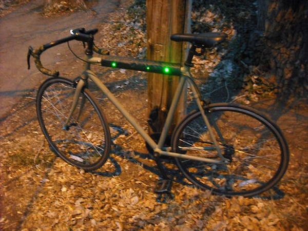
Well it’s that time of year again. That’s right, the sun is going down early, and it’s getting hard to avoid logging some miles on your bike after dark. You likely have great lights front and rear already, but what about on the sides of your bike? When crossing intersections, and cruising down those long stretches of unlit roads, a biker can be easy to miss.
Say hello to the led clad top tube pad. Not only does it provide a little protection for your bikes paint job. It also provides a lot of protection for you when riding in the dark. When I sought out to build this project, I had some simple goals in mind.
1. It needs to be self contained
2. It needs to bring lots of attention to the bike with out distracting the cyclist.
3. It needs to look clean
With this in mind it was time to put together a shopping list.
Step 1: Time to pick up some new toys.
Here is what we need to put this together.
We can get all of our parts from Sparkfun. I have also included the code for this project later in the instructable.
Arduino Pro mini x1
If your new to the Pro series Arduino, you will also need an FTDI basic. This let’s us program the Pro mini over usb.
LEDs x11
Resistors x 11
Wire Wrap Wire x an assortment of colors. Probably no less than 4 colors.
Battery x1
Don’t forget a charger. Lipos need a special charger to keep them from exploding.
Step 2: I hope you have your thinking caps on.
Let’s take a moment to explain exactly what is going on under the hood. This step is going to be a bit of a data dump, but this will be very useful information when your putting this together, and working with the code. This is important to understand before going further. We’ll get to the fun part soon enough.
I have used tri color leds so that we can use a whole variety of colors to match your mood, and your bike. The system is a bit complicated because of these leds though. Tri color leds have 4 pins. 1 is ground, and the other 3 are color pins (Red, Green, Blue). In a normal set up you would usually connect the ground to the Arduino ground, and pull each color pin high to change colors. In this system that would mean with 11 leds, 3 colors each, we would need 33 I/O pins!
Unless we strap a Arduino Mega to this thing, there’s no way that we can make that work. So here are a few tricks that I pulled to get the pins down to a more respectable number.
Let’s look at the layout. Instead of wiring it like this
–1—2—3—4–
—-5—6—7—–
–8–9–10–11–
We will wire it like this.
–1—3—5—7–
—-2—4—6—–
–1—3—5—7–
By strategically wiring two leds to act as one, we cut down that initial 33 to 21. But that still won’t cut it, we need to bring that down even more. So the next trick, instead of giving each led it’s own I/O pins for color, we will make all 11 leds share the same I/O pin for each color.
Why you ask? This way we only need 3 pins. This brings down that 21 to 3. Much better, But wait… If they all share an I/O pin won’t they all just turn on and off at the same time?
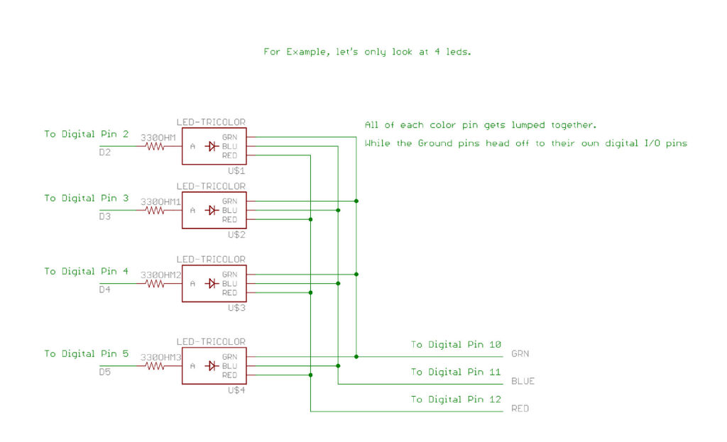
Remember that tricolor leds have four pins? 33 pins only considered the color pins. We still haven’t done anything with the ground pins.
We will give each ground pin an I/O line of it’s own. This will let us control which leds are on and off by toggling the Ground pin low, when a color pin is high. We change the color by toggling different color pins high. If Blue is HIGH, green and red, are low, and 1, and 3’s ground are low, and 2,4,5,6,7’s grounds are high, only 1, and 3 will be on and will be blue.
If you want all of the leds off, you can simply pull the 3 color I/O’s LOW.
Make sense? I hope so. Make sure to look at the schematic below, it should help some.
For more detail: Flashing LED Top Tube Pad for your bike using Arduino