As thefts are increasing day by day security is becoming a major concern nowadays. In this project we will make a digital door lock system with keypad using Arduino Uno. It will open your door only when the right password is entered and it will start beeping when a wrong password is entered.

Components Required
- 4×4 keypad
- LCD
- Arduino Uno
- Push Pull Solenoid
- TIP 120 NPN transistor
- Power Supply
- Breadboard
- 1KΩ, 220Ω Resistor
- 10KΩ Potentiometer
- Buzzer
- Connecting wires
Circuit Diagram & Explanation
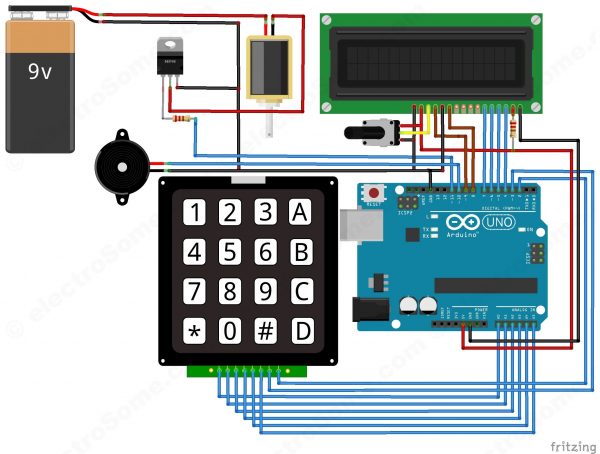
First of all, we will make the connection to the 4×4 Keypad. For connecting the keypad with the Arduino we are using both analog and digital pins. We used analog pins since we need more that 14 digitals pins for this project. If you are using Arduino Mega, then there is no need to use analog pins. Connect first six pins of keypad to analog pins A0 ~ A5 of Arduino and remaining two to digital pins 3 and 2.
To connect the push pull solenoid with the Arduino, we will have to use external power because it requires 6 ~ 12V to operate and much more current than the Arduino can provide. So to do that, we will use TIP120 NPN transistor as a switch/driver and a DC power source which can provide 6 ~ 12V. The NPN transistor will switch ON when we will give HIGH to its base. So, connect its first pin (which is the base pin) to the pin 11 through to a 1KΩ resistor, second pin (which is the collector pin) to the negative wire of push pull solenoid and third pin (which is the emitter pin) to the ground. Now connect the positive of power supply to the positive wire of solenoid and the negative of power supply to the ground.
Now connect the positive wire of buzzer to the pin 10 of Arduino and negative wire to the ground.
Now we will connect the 16×2 LCD to the Arduino.
- Connect pin 1 (VEE) to the ground.
- Connect pin 2 (VDD or VCC) to the 5V of the Arduino.
- Connect pin 3 (V0) to the middle pin of the 10KΩ potentiometer and connect the other two ends of the potentiometer to VCC and GND. The potentiometer is used to control the contrast of the LCD.
- Connect pin 4 (RS) to the pin 9 of the Arduino. This is Register Select pin used to select a particular register in the LCD driver, which is handled by the LCD library.
- Connect pin 5 (Read/Write) to the ground of Arduino. This pin is not often used so we will connect it to the ground as we are only writing data to LCD.
- Connect pin 6 (E) to the pin 8 of the Arduino. It is used indicate a valid data or command in the following data pins.
- The following four pins are data pins which are used to send data or commands to the LCD.
- Connect pin 11 (D4) to pin 7 of Arduino.
- Connect pin 12 (D5) to pin 6 of Arduino.
- Connect pin 13 (D6) to pin 5 of Arduino.
- Connect pin 14 (D7) to pin 4 of Arduino.
- Connect pin 15 to the VCC through the 220 ohm resistor. By changing this resitor value we can change the backlight LED brightness. Larger values will make the back light much more darker.
- Connect pin 16 to the Ground.
Working
In this project, we have used EEPROM in the Arduino to store the password in it. The default password stored in it will be ‘1234’. When we enter a password, it will match it with the password stored in the Arduino EEPROM. If it is correct, then it will show ‘Passkey Accepted’ and the push pull solenoid will come in low state (Door Unlocked). If the password is wrong, then it will show ‘Access Denied’. During this condition the buzzer will start beeping and the push pull solenoid will remain in the high state (Door Locked). The buzzer will also beep once when any key is pressed.
For changing the passkey, we have to press ‘#’. When we press ‘#’, it will ask for current passkey. If we enter the correct password it will ask for new passkey and will save it in the EEPROM.
Read More: Digital Door Lock using Arduino