Step 1: The case
Step 2: Voltage Divider
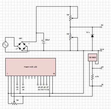
 My first attempt at this was disappointing. When measuring a DC battery, my readings were rock solid. When reading the dc output of a bridge rectifier, they swung from full voltage to zero, and back again on a regular cycle. This was fixed by applying a capacitor across the output of the bridge rectifier, as per the schematic. If you will be monitoring a DC voltage, you can eliminate the capacitor and the bridge rectifier. The other part of the circuit is the 5.1v Zener diode from the Arduino input to Gnd. This is to prevent you from doing something foolish with the voltage divider, like presenting higher than 5v to the Arduino inputs. If the input goes higher than 5v, the Zener will conduct the excess to ground.
I calculated I needed a 3k and a 1k resistor for the voltage divider, but some adjustment might be necessary, so I used two 10k pots to give me the ability to fine tune the output.
Before connecting the output of the voltage divider to the Arduino, I plugged my DMM into the output of the voltage divider, connected the AC source, and adjusted the two pots till I got exactly 5v. Again, the 5.1v Zener prevents you from doing something foolish with the pots.
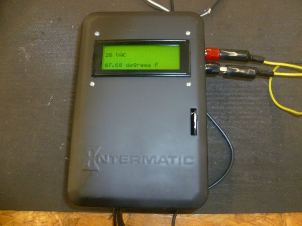
I then connected my DMM to the AC source, took the AC reading, and put it into my map command in the code as the value for 1023 on the ADC. After all the wiring was finished and the code uploaded to the Arduino, I connected the input of my AC transformer to a variac so I could run the transformer primary from 0-125vac. With my DMM on the secondary of my 29vac transformer, the Arduino LCD display mirrored the DMM almost perfectly throughout the complete range.
Arduino code as follows:
int voltPin = 0; // voltage divider (middle terminal) connected to analog pin 0
// outside leads to 0-29vac
void setup()
{
Serial.begin(9600); // setup serial}
void loop()
{val = analogRead(voltPin); // read the input pin
Serial.println(val); // debug value
volt = map(val, 0, 1023, 0, 29); // map 29v range
Serial.println(volt); // voltage
delay(50);}
Step 3: Temperature – TMP36
{Serial.begin(9600); // setup serial}
void loop()
{int reading = analogRead(tempPin); // read the input pin
float voltage = reading * 5.0;
voltage /= 1024.0;
 Serial.print(voltage);
Serial.println(” volts”);
float temperatureC = (voltage – 0.5) * 100;
Serial.print(temperatureC);
Serial.println(” degrees C”);
float temperatureF = (temperatureC * 9.0 / 5.0) + 32.0;
Serial.print(temperatureF);
Serial.println(” degrees F”);
delay(500);}
Step 4: Using DS18B20 Sensors
To use the DS18B20, you need two library files (updated for Arduino 1.0), and you need to find the address of your sensor. Library files and sketches to find your address can be found at
http://www.hacktronics.com/Tutorials/arduino-1-wire-tutorial.html
http://www.hacktronics.com/Tutorials/arduino-1-wire-address-finder.html
For more detail: Digital Arduino Voltmeter with Temperature