Concepts
So you know what a switch is, but what can you do with it?
One of the uses of a switch is to tell the controller to activate/deactivate different components. In this case we are going to use the switch to turn on and off an LED. We will do this by checking to see if the switch is pressed. When it is pressed, we will turn on the LED. when it is released, we will turn off the LED.
Wiring up the components
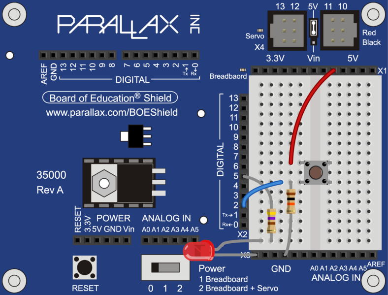
To create the circuit you will need to connect a switch as an input and an LED as an output to the Arduino. This means that you will need a switch, an LED, a 10kΩ resistor, a 470Ω resistor, a blue or yellow jumper wire, and a red jumper wire.
Connecting the LED
The wiring for the LED is very similar to when we first introduced the LED.
Connecting the switch
Now you need to connect the switch. First, let us look at the schematic of the circuit to get an idea of what you need to do.
The Arduino pin is connected to the circuit between the resistor and the switch. This is because the digital pin is configured such that it needs a small amount of power to change states. This is useful since we don’t want to draw too much power through the Arduino. However, this also means that if the pin is not connected to a known level in the circuit, it could have any value. This is called floating, since the value of the pin is neither high nor low.
To solve this problem we use the resistor to connect the pin to ground. We use a resistor and not just a wire so that we can limit how much current is flowing through the connection. Since we want to minimize the power draw we will use a large resistor, in this case 10kΩ. When the switch is not pressed the pin is only connected to ground through the resistor. Since the pin will have what ever voltage value is applied to it, the resistor can be considered as a wire when the switch is not pressed. However, once the switch is pressed, the pin is directly connected to 5V and the resistor limits the current flowing to just 0.5 mA, and thus prevents a short circuit.
Programming

Configuring ROBOTC
Now that we have everything connected, we need to tell ROBOTC how to configure the pins before we can program. We need to tell ROBOTC that we are using the Parallax BOE Shield, and that we have the LED connected to pin 5. We also need to tell ROBOTC that pin 2 is a Digital High Impedance (the led switch with the resistor connected to ground) and name it “ledSwitch”.
Read more: Controlling an LED using a switch