In this project, we will demonstrate how to build temperature sensor circuit using a TMP36 sensor.
As a temperature sensor, the circuit will read the temperature of the surrounding environment and relay the temperature to us back in degrees fahrenheit.
The IC we will use to measure the temperature is the TMP36 IC. We will integrate this with the arduino to measure the temperature. The arduino will then read this measured value from the TMP36 and translate into degrees fahrenheit and celsius, which we will be able to read from the computer from the arduino serial monitor.
Components Needed to Build the TMP36 Temperature Sensor Circuit
- Arduino Board
- TMP36 Temperature Sensor IC
- Computer
- USB with type A and B connectors
We can use any type of arduino board.
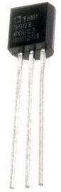
The TMP36 is a low voltage IC which uses between 2.7V and 5.5V of power. This is ideal because the arduino’s power pin gives out 5V of power. The IC has just 3 pins, 2 for the power supply and one for the analog output. The output pin provides a voltage output that is linearly proportional to the celsius (centigrade) temperature. In order to get the temperature in fahrenheit, we have to write code to the arduino to convert this celsius temperature into fahrenheit. The code is shown below.
Below is the pinout of the TMP36 IC:
Pin 1 receives positive DC voltage in order for the IC to work. This, again, is voltage between 2.7-5.5V. Pin 3 is the ground, so it receives the ground or negative terminal of the DC power supply. And Pin 2 is the output of the IC, outputting an analog voltage in porportion to the temperature it measures.
This is the datasheet of the TMP36 IC: TMP36 Temperature Sensor IC Datasheet.
The arduino, with suitable code, can then interpret this measured analog voltage and output to us the temperature in degrees fahrenheit.
Also to do this project we need a USB cable with a Type A connector on one end and a Type B connector on the other end. This is so that we can hook our arduino to a computer and send it code that it can run to dispaly to us the temperature.
Temperature Sensor Circuit Schematic
The temperature sensor circuit we will build is shown below:
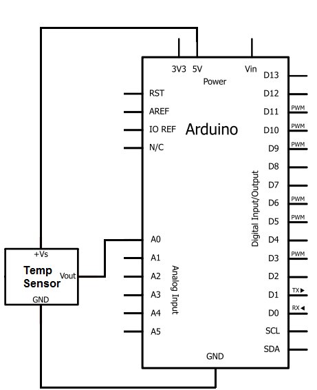
So you circuit connections are:
Pin 1 of the TMP36 goes into +5V of the arduino
Pin 2 of the TMP36 goes into analog pin A0 of the arduino
Pin 3 of the TMP36 goes into ground (GND) of the arduino
Now that we have this circuit setup, we now connect the USB cable from the arduino to the computer. The type B side of the connector goes into the arduino and the type A side into the USB port of the computer. Now the computer is connected to the arduino. We can now write code in the processing software to give instructions to the arduino.
For more detail: How to Build a TMP36 Temperature Sensor Circuit