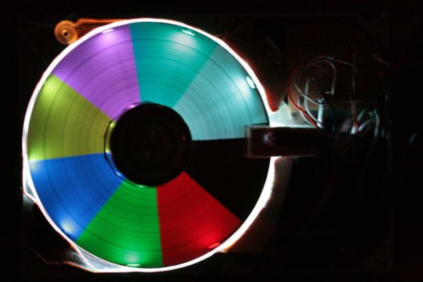
The platter of a hard drive spins well over sixty times a second. If a narrow slot was cut into the platter to allow LEDs to shine through, we can achieve flicker fusion and trick the eye into seeing a stable image. This phenomenon is known as persistence of vision (POV). There are many examples of LEDs being used for POV, building an image by moving the LEDs or having the observer move relative to them. The LEDs used in this project do not move, and the image is built using the interference of the slotted, spinning platter.
The system works by timing the slot in the platter. The Arduino uses an internal timer to clock each revolution. It achieves this using an infrared gate, which triggers a hardware interrupt on every full revolution of the platter. The Arduino uses the revolution time and phase to schedule a second internal timer. This second timer uses an interrupt to schedule the timing of the LEDs, firing tens of thousands times a second to build a stable, visible image.
This work is based on Ian Smith’s version of the same. His work is excellent, and his website on this topic will help provide a complete picture for this instructable.
Step 1: Gather Materials
Hard Drives – You will need to gather a few unused hard drives. It’s no problem if they no longer function, but it’s imperative that the candidate hard drive can spin indefinitely when it’s powered.
Arduino – If you don’t have an Arduino board, this link will show you where you can buy one. I developed this with a Diecimila, but I would expect the code to work on a Duemilanove without changes.
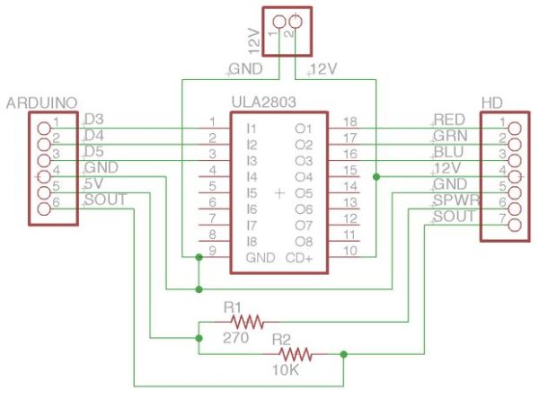
ULN2803A – This is responsible for switching the high current 12V LEDs.
Digi-Key: ULN2803APG-ND
RGB LED Tape – The best source I’ve found for tricolor LED tape is from Super Bright LEDs. A single 19.5″ strip costs $19.95.
Super Bright LEDs: NFLS-RGB15
270 Ohm Resistor – Limits current to your sensor source.
Digi-Key: 270H-ND
10K Resistor – Pull-up for your sensor output.
Digi-Key: 10KH-ND
You can build the platter sensor from either an infrared gate or a Hall-effect sensor. The infrared gate uses the slot cut out of the platter to disrupt the beam. The Hall-effect sensor will require that you glue a small but strong magnet exactly 180 degrees from the slot in the platter.
If you decide to use an infrared gate, you can either build your own gate from scratch or you can buy a manufactured gate. If you choose to build your own, you can use any old pair of infrared emitter/phototransistors (mine are from Radio Shack), or you can purchase the following:
Infrared Emitter – Used to provide an infrared beam to time the platter.
Digi-Key: 475-2648-ND
Infrared Phototransistor – Provides a pulse on every platter revolution.
Digi-Key: 475-1080-ND
I did not build my rig with a Hall-effect sensor. I chose to use infrared because I had the parts lying around, but a Hall-effect sensor is less obtrusive. If you choose to go the Hall-effect route, you will need to adjust a few details in this tutorial. For example, you will need to glue a magnet directly opposite of the slot. This will require changing the code loaded onto the Arduino to account for the 180 degree change in phase.
I have not tested this Hall-effect sensor, but I would expect it to work fine:
Hall-Effect Sensor – Provides a pulse on every platter revolution.
Digi-Key: 620-1001-ND
Step 2: Deconstruct a few Hard Drives
You will be destroying any hard drive you open. If you still intend to store or access data on a drive, it’s a bad idea for this instructable.
Not all hard drives are alike, but they are remarkably similar. From brand to brand, they often have mechanically interchangeable parts such as platters, spacers, retaining collars and screws. In order to build my version, I had to take apart five hard drives to achieve the right configuration of parts and hard drive chassis.
The motor that spins the platter is known as the spindle. Most hard drive spindles are three terminal brushless motors. Driving this kind of motor is beyond the scope of this tutorial. To our advantage, most logic boards for hard drives will spin their spindle indefinitely.
Select a hard drive, and open the top case. Opening a hard drive requires a set of Torx screwdrivers. If you don’t have any, you can pick up a set at any well stocked hardware store. Once you remove the top case, remove the entire read/write assembly. Be careful not to damage the underlying logic board, as it is required to drive the spindle.
Remove the platter retaining collar, and remove the platter stack. Make sure you save the collar, its screws, any spacers and any platters.
Here are a few important issues to be aware of as you proceed to select your candidate drive:
– The clearing of the platter over the LEDs is critical, and there is a very small space to fit them in. Once the LEDs are glued to the wall of the platter chamber, the platter must be able to freely spin. This means no part of the LEDs or its ribbon backing can touch the platter. It’s important to test this before gluing anything to anything.
– The LEDs are too tall to hide below the first platter. The solution is to use a combination of spacers from various hard drive manufacturers to shim a single platter above the LEDs. This can be very tricky to achieve, and may have you tearing apart working computers in sacrifice to the cause.
– Once you have all of the above figured out, make sure you test the spindle driver! Screw it together (without the LEDs) and plug it in. Make sure the drive spins continuously! I had the perfect drive that would only spin for about a minute before quitting. I suspect it found the lack of a read/write head unsettling, and decided rest was best. The point is you don’t want to carry out the remainder of this instructable with a drive that won’t continuously spin for you.
Step 3: Cut out Paper Platter
Most hard drives are finished with a black matte. It is not a conducive background for our LEDs, so we need to make a more reflective backdrop.
Grab a piece of thick, white paper and trace the outline of a platter (both the inside and outside). Cut out your paper platter, and widen the central hole a few millimeters. Slip this over the spindle, and push it down to the floor of the platter chamber. You might need to trim the paper a little so it doesn’t rip. This will serve as a white, reflective backing, making the color in your LEDs shine more vibrantly.
Once the backdrop is positioned, make sure the spindle can still spin freely. If it can’t, trim the center hole of your backdrop.
Step 4: Build LED Bridges
The gap created by the read/write head assembly will not allow us to fully encircle the platter with LED tape. In order to bridge the gap, you need two build two bridges. I made mine out of half-inch thick wood, but any material should work. It just needs to have a smooth surface, half an inch thick.
If you are building the bridges out of wood, you will want to use a band saw. The pictures will help guide you.
Using a platter as a template, mark out a half-circle from your material. Make sure there is ample material around your half-circle. Cut out your half-circle, and toss it. Use the remaining outline to build the bridge from.
Line up your circle outline with the platter chamber. Mark off extra material, and trim it. This might take a few iterations to get right. You should be left with a roughly 1″ thin, 3.5″ wide U-shape. Once you have this shape, measure the center, and mark half an inch on either side. Remove this center.
You now should have two curved pieces. Test fit them on either side of the chamber gap. You might find that knobby features of the chassis require further refining of a certain bridge. Continue to cut away material until they you have a snug fit. The chamber wall should be flush with your bridges, or the LEDs will mount askew. Make sure the platter can spin freely with the bridges in position, shaving down any excess material.
Grab some strong, quick setting glue and glue each bridge to their position. Make sure to hold the bridge down until the glue sets.
Step 5: Cut the LED Tape
In order to achieve the best effect, you will want to fully encircle the underneath of the platter with the LED tape. If you are using a standard 3.5″ drive, then your platter chamber with bridges should accommodate nine LEDs.
The LED tape can be separated into groups of three. Cut out one section of three groups. Do not separate the tape into three groups. You want one piece of tape with nine LEDs. This should leave a reasonable gap for the platter sensor, where the read/write assembly used to sit. Make sure you cut the tape on the line between copper tabs, or else you may severe internal traces rendering the affected section useless.
Step 6: Solder Wires to the LED Tape
If you don’t have wires pre-attached to the section you wish to use, you will need to solder on wires. Identify the red, green, blue and 12V lines, and solder four wires to the copper tabs. It’s best if you tin the copper pads before soldering the wires. After you attach your wires, be mindful of the stress you apply to the solder joints, they can easily break. Test your work using a 12V supply.
For more detail: Hard Drive Persistence of Vision (HDPOV)