This is a trial and error / design and development process which I followed in developing a camera slider for creating time-lapse video clips on my DSLR camera.
The idea came from using standard Aluminium extrusions I have available at hardware stores, and create a slider chassis / dolly which is able to slide along this extrusion. The Aluminium extrusion is what builders use for creating a smooth screed on a floor, or plastering a wall. It is a perfect hollow rectangular extrude, of approx 70mm by 20mm, and is available in various lengths between 1m, and 4m. The wheels which I found which are suitable are standard Hillaldam shower rollers, which ended up working perfectly.
The process of development saw the following needing to be designed, tested, and then prototyped:
1. Slider Rail (standard Section)
2. Camera Dolly / Slider (rollers attached to a bent metal chassis)
3. Motion Control: this was the most tricky and takes up most of this instructable. It illustrates how I developed and tested a standard geared motor, with a gearbox… which didn’t work well enough. After this, I attempted utilising a stepper motor which is controlled by an Arduino Uno board which worked much more effectively. I am unable to provide set plans which you can follow, as my design depended heavily on the resourses which I had available to me (South Africa). The availability of components to me is not as diverse as in the US and Europoe, and please keep this in mind when commenting.
For the planning and design work, I used Corel Draw. This is also what I used for designing the cogs and gear layouts which were lasercut.
The designing of the gears was done with the assistance of one of the most useful online generators, being Woodgears.ca, This allowed me to save the files as HPGL, and import directly into Corel Draw.
With regards to the the actual time-lapse clips, this is all done with Magic Lantern, which is installed on my Canon 500D DSLR camera. It allows me to utilise the incorporated Intervalometer for taking timelapse images. Furthermore (my favorite) is to film video and override the initial 30 frames per second and make it film at one frame per second. When it plays back, it is 30 times normal speed which is extremely effective. This needs to be compensated with a Neutral Density filter, and Exposure compensation (with Magic Lantern).
Step 1: Geared motor and necessary hardware for Gearbox Mark I
The first idea I had was to use a geared motor (30 RPM if I am not mistaken) to drive a set of gears, which reels a spool of fishing gut. This is to slowly drag the slider along the rail.
Required: Geared Motor (12V) & 12 V battery.
Perspex: For cutting the gears.
Bearings: Friction fit into holes cut within the gears.
Fishing Gut
Bobbin: to wind up the fishing gut onto the output drive.
And fasteners for assembling.
I wont go into too much detail here, as the outcome was unsatisfactory, ineffective, jolty, frustrating, and still far too fast. There was no area for adjustment, and I went back to the drawing board (CorelDraw).
Step 2: Geared motor and Gearbox Mark II
I used the same basic hardware as Mark I, however wanted to further gear down the motion. I am unsure exactly the gearing ratio (but I know this can be calculated).
I developed a bobbin holder which would allow for the easy removal and re-winding of the spool of fishing gut.
You can see that the careful planning in CorelDraw translated effectively into the assembled gearbox unit. The final outcome is extremely fragile, cumbersome and difficult to use.
Although I was very happy with the feel of the fabricated prototype: functionally it did not allow me the versatility needed in experimenting with the timelapse. this unit is still limited to one single speed. I could however fabricate bobbins of different diameters to manipulate the spool gearing, however this is where I realised that Arduino is the next door to knock on.
Step 3: Arduino Uno + Stepper Motor
The inability to easily manipulate gearing, together with the hassle of the fishing gut, let me to begin my Arduino learning. What I wanted, was to have a small driving gear and control the rotation of this with the Arduino. I want to be able to save different settings as different sketches, and upload whichever I would like. Through more experimentation I would be able to create a collection of settings for different applications. I know some of the capabilities of the Arduino, however my almost non-existent electronics understanding has prevented me from learning sooner.
I bought a small stepper motor and shield off of ebay, and luckily it reached South Africa without much hassle (i.e. luckily it didnt get pinched in the postal system).
I learnt the basics from the Arduino forum, and used sample stepper motor code as a starting point. You can see a paper clip on the stepper motor shaft, which I was able to step back and forth. The final code which I ended up using looked a bit like this…
/* YourDuino.com Example Software Sketch
Small Stepper Motor and Driver V1.4 11/30/2013 http://arduino-direct.com/sunshop/index.php?l=pro… Steps one revolution of output shaft, then back [email protected] *
*—–( Import needed libraries )—–*/ #include
/*—–( Declare Constants, Pin Numbers )—–*/ //—( Number of steps per revolution of INTERNAL motor in 4-step mode )— #define STEPS_PER_MOTOR_REVOLUTION 32
//—( Steps per OUTPUT SHAFT of gear reduction )— #define STEPS_PER_OUTPUT_REVOLUTION 32 * 1 //2048
/*—–( Declare objects )—–*/ // create an instance of the stepper class, specifying // the number of steps of the motor and the pins it’s // attached to
//The pin connections need to be 4 pins connected // to Motor Driver In1, In2, In3, In4 and then the pins entered // here in the sequence 1-3-2-4 for proper sequencing Stepper small_stepper(STEPS_PER_MOTOR_REVOLUTION, 8, 10, 9, 11);
/*—–( Declare Variables )—–*/ int Steps2Take;
void setup() /*—-( SETUP: RUNS ONCE )—-*/ { // Nothing (Stepper Library sets pins as outputs) }/*–(end setup )—*/
void loop() /*—-( LOOP: RUNS CONSTANTLY )—-*/ { Steps2Take = STEPS_PER_OUTPUT_REVOLUTION ; // Rotate CW 1 turn small_stepper.setSpeed(100); small_stepper.step(Steps2Take); delay(2000); }/* –(end main loop )– *
* ( THE END ) */
I manipulated the different values to reach different outcomes. I do not understand the code very well, but it works. I was able to rotate the drive shave a fraction of a turn; and control the time between these small steps. This coupled with the intervalometer within the camera, I would be able to achive what I initially wanted. I know you are able to trigger the camera with an Arduino Intervalometer, however tackling the motion control is a suitable first step for me on my Arduino adventures.
If you have any comments about my code… PLEASE feel free to let me know what you think, how I can simplify it or attempt alternatives.
Once I got the circuit working, it was then time to attempt to adapt it onto the camera slider & rail.
Step 4: Adapting the slider chassis to accommodate the hardware components.
I was lucky that the amount of room below the slider was able to accommodate the Arduino Board.
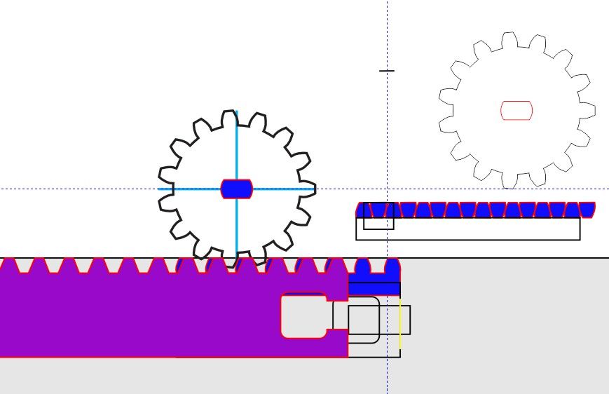
I decided to mount the stepper mounter on the slider chassis, and this needed a small gear which would meet teeth on the slider. This would allow me to use the one chassis on different lengths of rail.
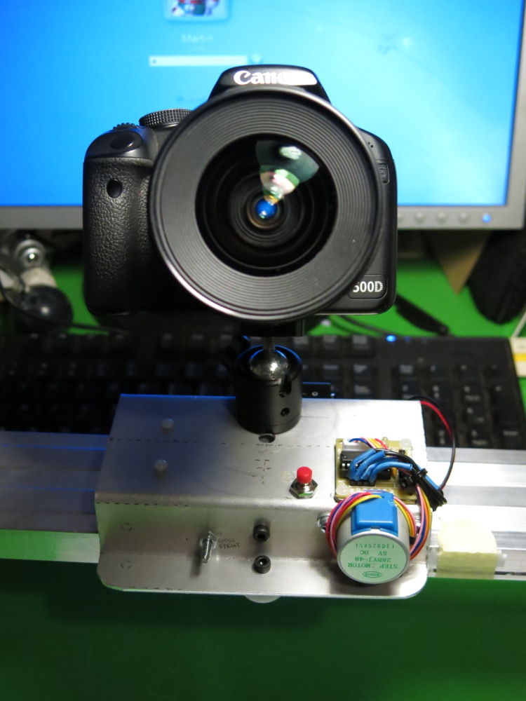
I tinkered with all the components and tried different arrangements until I found something which I was happy with. this allowed me to mount the following, all on the slider chassis: Arduino Uno Board, 9V battery, 5v Stepper Motor, 5v Stepper Motor Shield, On/Off toggle switch between the battery and the Uno. The images communicate a lot more than what I explain here, but you can see how using the Aluminium sheet allowed me to easily mark, drill and tap holes. With careful planning and dry assembling, I was able to create a neat, lightweight and effective control unit. I just needed to make sure it would assemble effectively onto the slider rail before I could assess whether or not it will work.
Step 5: Adding rail of teeth to the extrusion.
I worked from the standard gearing I decided on for the previous geared components, and adapted it in CorelDraw, to suit a linear rail. I had to make the rail narrow enough not to collide with the rollers.
Using a glue called Joiners Mate, I glued sections of the rail to the edge of the slider rail. You can see that I first tested a section and once I knew the exact position I glued the rest to the entire length of the rail.
For more detail: Arduino+Stepper Motor Camera Slider