The Arduino Project Board is basically a board to transer your ATMEGA168/328 to when you have completed your project and no longer need to use the Arduino as a development board. Simply transfer the programmed chip from the Arduino board to the Arduino project board and you are in business. Now your Arduino is no longer tied up in your finished project and you have a simple breakout board to work with independently of the Arduino.
Here are some basic instructions for assembling it and getting started.
Step 1: Go get stuff:
The complete Arduino Project Board Kit includes:
(x1) Arduino Project Board PCB (or you can make your own with ProjectBoard.pcb)
(x1) Bootloaded ATMEGA328 chip
(x1) 28-pin socket
(x1) 16 mhz crystal
(x2) 22pF capacitors
(x1) 0.1uF, 25V capacitor
(x1) 10uF – 47uF, 25V capacitor
(x1) 1K, 1/4 watt resistor
(x1) tactile switch
(x1) 7805 regulator
(x1) 9V battery clip
Step 2: Resistor
Solder the 1K resistor to R1 on the board.
Don’t forget to clip away the excess leads from the back side of the board.
Step 3: 0.1uF Capacitor
Step 4: 22pF Capacitors
Step 5: Switch it up
Line up the switch with SW1. Then press it down until it “pops” in and becomes flush with the board.
Solder it in place.
Step 6: Crystal
Step 7: Socket to me
Put the socket atop the spot for the Arduino. Make certain that the notch cut into the end of the socket is located next to the 1K resistor.
Solder all 28 pins in place.
Step 8: Electrolytic Capacitor
Solder the electrolytic capacitor in the spot labeled C3.
Don’t forget to make sure the “-” stripe on the capacitor is opposite from the + label on the board.
Step 9: Regulate
Add the LM7805 voltage regulator to the board in the spot labeled 7805.
The metal plate on the back of the regulator should be on the side opposite of the capacitors.
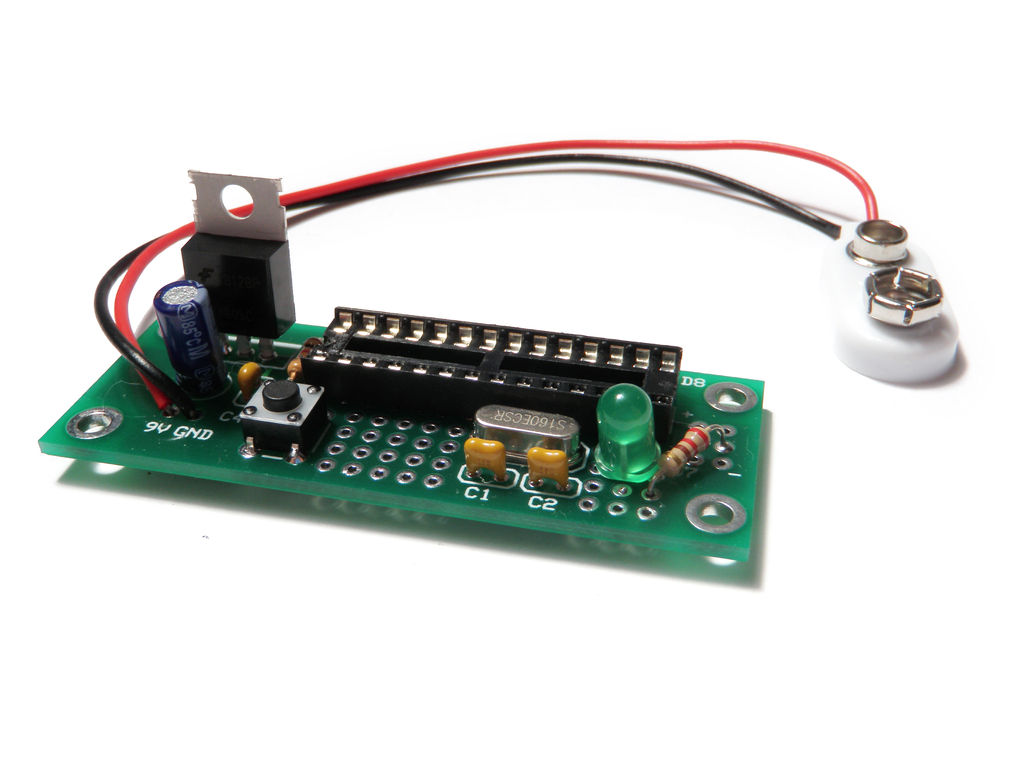
Step 10: 9V Connector
Step 11: Test LED (optional)
I added a test LED to the board of this example to demonstrate it is working.
I suggest that you don’t do this if you don’t have to and only add the parts you need for your project.
Anyhow… in this example the LED is connected to Pin 12 (Digital Pin 6) and then to ground through a 220 ohm resistor.
Step 12: Program and transfer
Program your chip and transfer it to the board.
Here is the blink code for the LED example shown in Step 11:
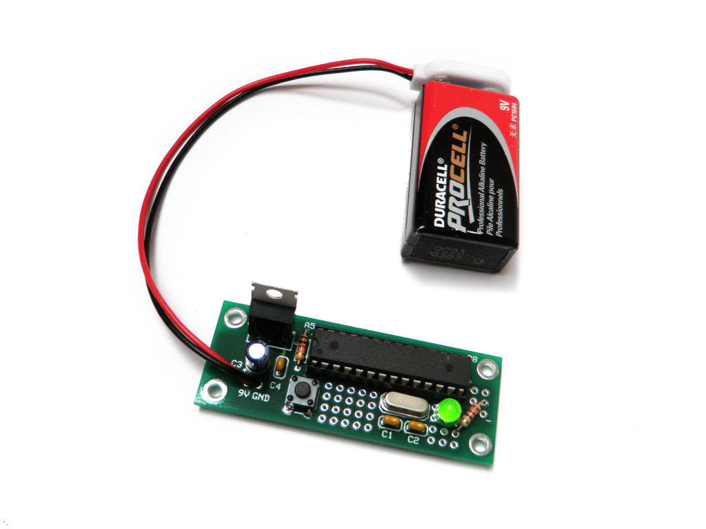
Step 13: Power!
Plug in a 9V battery and it should be good to go.
For more detail: Arduino Project Board