In this post I’d like to describe you a project I’m working on that consists of connecting an Android development board to one (or more) Arduino slave(s) using modbus protocol and rs485.
Even though the idea of this project could be applied in many fields, I chose to contextualize it in a typical smart home context: a touch display that dims lights, shows temperatures and bulbs statuses.
The nice feature of the development board I used is that it has many interfaces such as Ethernet, rs485, rs232 and I²C as well.
I expressly selected rs485 because Arduino-based microcontrollers are not ready for Ethernet yet (even though some examples still exist but without great success). Indeed, rs485 is a well known standard that has been widely used in the industrial context and in building automation applications. It is a half-duplex, 2-wires, low noise bus that allows high speeds and remote devices connection (up to 1200 meters).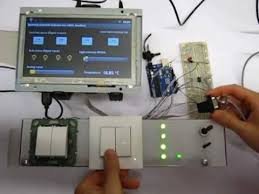 Furthermore, modbus is a serial communication protocol, developed for industrial applications, open and easy to deploy and maintain. I used modbus RTU, but other variations of the protocol still exist though.
I divided the project into core parts, namely:
Electrical parts
The key ingredients for this project are the following:
- An Android based multi touch panel
- One (or more) Arduino board (not necessarily Mega)
- A Maxim’s Max485 chip (or eventually a cheaper one like TI’s sn75176a)
- Led
- A temperature sensor (like TMP36)
- Switches
- A potentiometer
- One 120 Ohm resistor (not used in this project because of the short distance of master and slave)
- Wires and some soldering experience
Circuit diagram
The picture on the right shows an overview of the circuit diagram of the project (some parts of the picture made with Fritzing). More than one Arduino board could be connected to the bus though.
Arduino sketch
Arduino sketch essentially uses SimpleSlaveModbus library (Tutorial on how to install a new Arduino library). I personally suggest you to take a look at documentation in order to have a better idea on how this library works.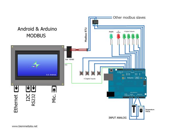 After including the modbus library header at the beginning of the source code,I declared an integer array (named holdingRegs) that stores the modbus registers. Function code 16 writes into them whereas function code 3 read them. The first two registers are reserved for analog values such as those gathered from A0 and A1 Arduino’s pins. INDIG0 to INDIG4 are served for digital inputs, OUTD0 to OUTD4 to digital outputs and AOUT0 for PWM.
In the setup section of the sketch, I call the modbus_configure function in order to configure the modbus with the following parameters: the baud rate, the ID of the slave (address), the transmit enable pin and the number of registers. Subsequently, I basically configure the digital Arduino pins with pinMode. In the loop of the sketch, I inserted a call to modbus_update specifying, as a first parameter, the reference to the array that stores the modbus registers. This function will take care of the received modbus commands and will modify the registers accordingly in case of writing or reading requests.
For more detail: Android Arduino Communication through Modbus and Rs485