This instructable shows you how to build a Web-enabled tri-color LED based on an Arduino and the WIZnet Ethernet shield, controllable from any Web browser .
Check the live demo at http://try.yaler.net/~arduino/led
Because the LED is exposed through a simple RESTful web service running on the Arduino color changes can also be triggered by Pachube or other platforms offering Web hooks. Welcome to the Web of Things ! The LED can of course be replaced by a motor or a high voltage switching relay to enable more interesting browser controlled applications, e.g. for home automation.
Publishing your Arduino through the Yaler relay server makes the Arduino accessible from everywhere even if it is hidden behind a firewall or a NAT and does not have a public IP address. A single Yaler relay server instance can host many Arduinos (and any other device with a TCP Socket library, e.g. a Sheevaplug or an Android phone) and is available for non-commercial use including full source code at http://yaler.org/ (Disclosure: I founded the company developing Yaler)
Tools
- Soldering iron
- Helping hands
- A / B USB cable
Infrastructure
- Internet access with DHCP, no public IP address needed for Arduino
- (Optional: PC or Cloud Server with a public IP address, to run Yaler)
Step 1: Soldering resistors and wire to the tri-color LED
(Note: All images show the Ladyada LED with the corresponding resistors and wire color)
- Shorten all except for the longest leg of the LED
- Solder the resistors to the LED legs as shown below
- Shorten the remaining long leg
- If you use the Ladyada LED, solder the red wire to it [as shown below]
- If you use the SparkFun LED, solder the black wire to it
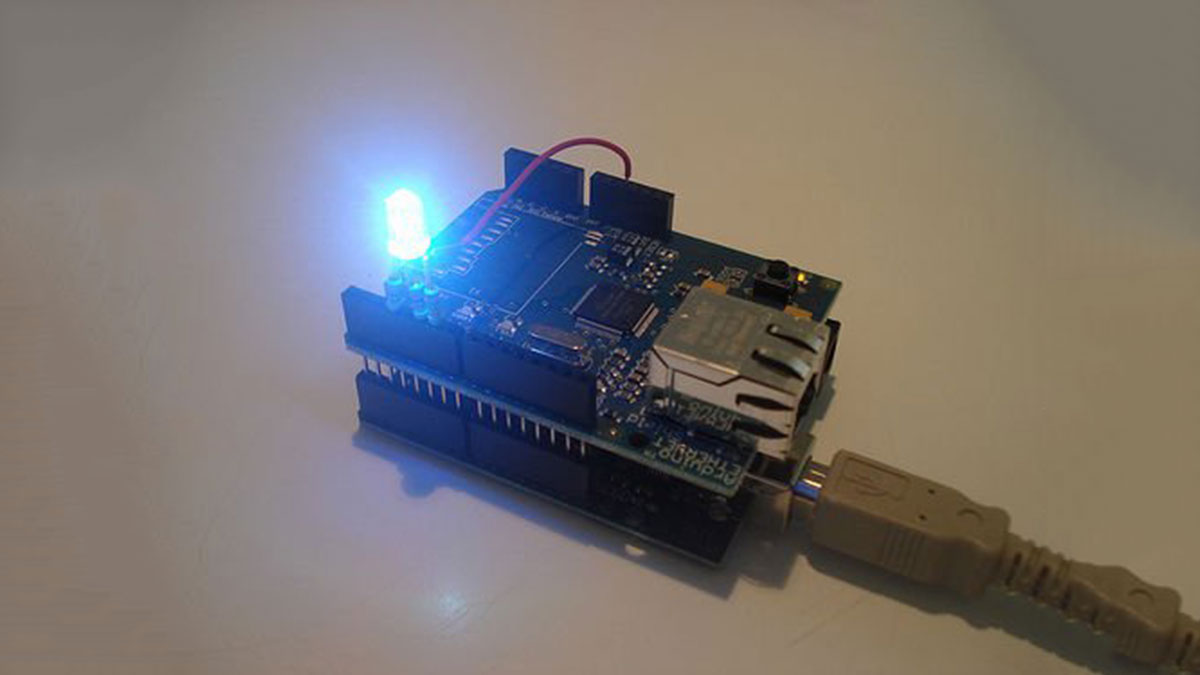
Step 2: Connecting the LED to the Ethernet shield
- Stack the Ethernet shield onto the Arduino
- Connect the LED to the pins 3, 5 and 6 (red) of the Ethernet shield
- If you use the Ladyada LED, connect the red wire with the 5V pin of the Ethernet shield
- If you use the SparkFun LED, connect the black wire with the GND pin of the Ethernet shield
For more detail: Web Controlled Arduino LED