The Arduino RFID lock
How does it work?
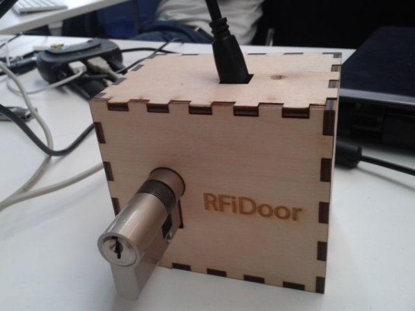
The Arduino RFID lock is a lock that can be opened easily, but is secure. The lock works with a server database that can register card codes. On the door there is a RFID reader connected to the lock. If the RFID reader reads a registered card the door will open. One of the pictures gives a schematic overview of the functionality of the Arduino RFID lock.
In this instructable there will be explained how to setup a database, how to connect the RFID reader and how to set up the Arduino controlled lock.
Step 1: The database
How to make?
Step 1: The database and PHP.
https://www.dropbox.com/s/i9jd5pv6qxrm6x2/Instructable.rar
This link has one file with all the codes in it. For the database use the PHP_final.rar.
Create a Mysql database that is named ‘doorsystem’ and exists of 4 columns:
– ‘id’,
– ‘rfid’,
– ‘name’,
– ‘password’.
In the upper image you can see the settings for the different columns. In the lower picture you see the different values for the columns. (Note the id is auto incremented so you don’t have to manually assign it, and works as the key for the database)
Make sure you add an account named ‘admin’, the php files will automatically assign admin privileges to this account.
When the database is online, open the connection.php file and enter the database connection data.
The rest of the files can be uploaded as is. Check the system by going to the index page and logging in with your admin account. Try adding some users.
Step 2: The Lock and Arduino
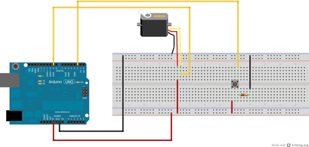
As you can see in the Fritzing file above, connecting the servo to the Arduino is as simple as connecting the 5v, ground and signal cables. To be able to use a button from the inside, this is also connected, with a pull down resistor, so when the button is pressed, it sends a signal to the Arduino.
For attaching the servo to the lock, you may need to drill some holes in the lock.
The red dots indicate where to drill the holes.
Put the screws through the holes of the servo, and then through the lock, to attach the servo firmly to the lock. Of course any other kind of binding material would work, e.g. we used duct-tape in the testing phase.
· Arduino (we used an Uno, but any kind is possible)
· Servo
· Breadboard
· RFID reader
· Mechanical cylindrical lock
For more detail: Arduino RFID Lock