This instructable is a quick write-up of my experience creating a multifunctional moodlight. Some basic knowledge of electronic circuits is expected. The project has not yet finished, some adding functionality and tweaking has to be done but it is already functional. If you guys are enthousiast about this instructable I will update it.

At the heart of the system is an Arduino. It will process the input from USB or each of the Capacitive touch inputs and control the RGB light.
This instructable is split into three sections:
– The capacitive touch section covers the invisible input buttons
– The moodlight section covers the controlling of the moodlight
– The ambilight section covers input by serial port, processing RGB values generated by a computer program to control the lights.
Disclaimer: Electronics can be dangerous, you yourself are responsible for any damage done. Some code is collected from forums and might not contain the name of its owner. Please let me know and I’ll add your name.
Step 1: Item list
The following components are needed for this instructable:
– Arduino+USB cable
– Breadboard
– Computer power supply
– 3x RGB strips, check out dealextreme.com.
– 3x TIP120 FETs, like http://uk.farnell.com/stmicroelectronics/tip120/darlington-transistor-to-220/dp/9804005
– A bunch of resistors (6* 10 kiloOhm, 3 * 2 megaOhm)
– A lot of wire.
– Tools
Capacitive touch
– Metal rings for groundplates
– Copper wire or plate
– Something to build it into (like a bookshelf:)
Step 2: Capacitive Touch – Basics & Circuit
Since I was painting my bookshelfs, I had the oppurtunity to ‘upgrade’ them as well. I wanted to control the moodlight by means of invisible touch. At first, my plan was to use a dedicated IC for this (like the Atmel QT240). But then I stumbled upon a page explaining that the Arduino can emulate a capacitive sensor by software.
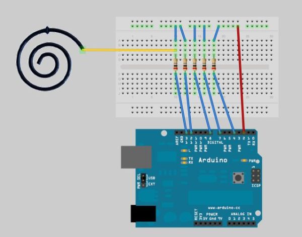
The electronic circuit can be found in the picture, the sensor is a spiralled copper wire (only one is shown for simplicity). Sensitivity is controlled by the resistors found before every pin. They can range from 1 MegaOhm (absolute touch) to 40 MegaOhm (12-24 inch away) depending on if absolute or near touch is needed (I ended up using 2M Ohm resistors). Experiment with the values until the sensor behaves like desired. It is a good idea to install some conducting surface (seperated by a thin non-conducting piece) connected to the circuits’ ground at the back of each spiral. This way the sensors will be more stable and less influenced by noise.
Some more pictures about installing the sensors in a bookshelf. A plug is installed as well for easy connection with the circuit later on. Filler is used to conceal everything, and after that they are ready to be painted.
Step 3: Capacitive Touch – Code & Testing
The following source code can be used on the Arduino for debugging, check the values with the arduino serial monitor. Six values are generated. The first is a measure of the performance of the system. The second to sixth are the sensed values on every pin. The values should rise when nearing your finger. If not, check for bad connections and interference. The resistor values can be changed to determine sensitivity. By implementing an if-then structure which is activated at a certain logical treshold, a switch can be made. This will be used in the final arduino code.
More information, suggested to read: http://www.arduino.cc/playground/Main/CapSense
— Arduino CapTouch Debugging Code —
#include
void setup() {
CapSense cs_2_3 = CapSense(2,4); // 10M resistor between pins 2 & 4, pin 4 is sensor pin, add wire, foil
CapSense cs_2_4 = CapSense(2,7); // 10M resistor between pins 2 & 7, pin 7 is sensor pin, add wire, foil
CapSense cs_2_5 = CapSense(2,8); // 10M resistor between pins 2 & 8, pin 8 is sensor pin, add wire, foil
CapSense cs_2_6 = CapSense(2,12); // 10M resistor between pins 2 & 12, pin 12 is sensor pin, add wire, foil
CapSense cs_2_7 = CapSense(2,13); // 10M resistor between pins 2 & 13, pin 13 is sensor pin, add wire, foil
void setup()
{
Serial.begin(9600);
}
void loop()
{
long start = millis();
long total1 = cs_2_3.capSense(30);
long total2 = cs_2_4.capSense(30);
long total3 = cs_2_5.capSense(30);
long total4 = cs_2_6.capSense(30);
long total5 = cs_2_7.capSense(30);
Serial.print(millis() – start); // check on performance in milliseconds
Serial.print(“\t”); // tab character for debug windown spacing
Serial.print(total1); // print sensor output 1
Serial.print(“\t”);
Serial.print(total2); // print sensor output 2
Serial.print(“\t”);
Serial.print(total3); // print sensor output 3
Serial.print(“\t”);
Serial.print(total4); // print sensor output 4
Serial.print(“\t”);
Serial.println(total5); // print sensor output 5
delay(10); // arbitrary delay to limit data to serial port
}
– Breadboard
– Computer power supply
For more detail: Capacitive touch Mood light using Arduino