Summary of Arduino Powered Mushroom Environment Control
The article details an Arduino-based environmental controller designed to monitor and regulate conditions for indoor oyster and shiitake mushroom cultivation. It uses two thermistors for temperature, an HS1100 humidity sensor, and an MG811 CO2 sensor to read environmental parameters. These inputs control four solid-state relays connected to heating pads, a sonic humidifier, and an air pump. The system employs voltage dividers and a 555 timer circuit to interface sensors with the Arduino, housed securely in boxes for stability and safety.
Parts used in the Arduino Powered Mushroom Environment Control:
- Arduino
- LCD Keypad shield
- 7-12 volt power supply
- USB cable
- Box to house components
- Veraboard/breadboard
- 4x solid state 5v-240v relays
- Mains power board with four sockets
- Wires
- Jiffy box for housing inline sockets and screws
- 10k Thermistors x2
- 10k Resistors x2
- HS1100 humidity sensor
- 555 CMOS timer
- Resistors: 576k, 49.9k, 1k, 909k
- Digital divide-by-ten chip
- MG811 CO2 sensor with op-amp amplifier breakout board
- 2x Heating pads
- Sonic humidifier
- Aquarium tubing
- Air pump (aquarium)
- Plastic airtight lunchbox
- HEPA filter for vacuum cleaner
- Hot glue gun
- Soldering iron
- Screwdrivers
- Multimeter
- Drill
This is my first Arduino project aimed at helping me with my other hobby which is growing oyster and shiitake mushrooms indoors.
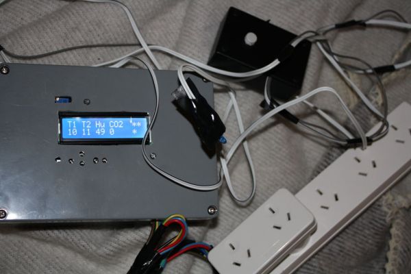
In a nutshell, the controller takes in two temperature readings, 1 Humidity reading and 1 Co2 reading and triggers a set of four relays connected to mains power.
Intended to be connected to the mains are two heating pads, a sonic humidifier and an air pump (although the choice isn’t limited to these of course).
Step 1: Items
MAIN:
-Arduino.
-LCD Keypad shield.
– 7-12 volt power supply.
– USB cable (socket that connects to USB on Arduino).
-Box To house the whole thing.
-Veraboard/breadboard.
– 4x solid state 5v- 240v relays.
– Mains Power board with four sockets.
– Wires.
– Jiffy box to house inline socket/screws to connect Sensors.
SENSORS:
-Thermistors 10k x2
-Resistor 10k x2
-HS1100 humidity reader
– 555 timer (cmos type)
– resistors: 576k, 49.9k, 1k and 909k
– Veraboard/breadboard
– Jiffy Box
– Digital divide by ten Chip
-MG811 C02 sensor (I got a breakout board with op-amp amplifier built in. You can make it yourself, it is a high precision op amp set up as non-inverting with gain around 10).
– Jiffy Box
ENVIRONMENTAL CONTROLLERS
– 2 x heating pads
– Sonic Humidifier
– Aquarium Tubing
– Air Pump (aquarium)
– Plastic lunchbox (airtight)
– HEPA Filter for Vacuum cleaner.
– Plastic tub
– Aquarium Air pump
– Aquarium Tubing
– Plastic Lunchbox (airtight)
– HEPA Filter for Vacuum cleaner
EXTRAS:
– Hot Glue gun
– Soldering Iron
– Screwdrivers
– Multimeter
– Drill
– Home brew larger.
Step 2: Thermistors
Solder two wires to each thermistor.
On a breadboard solder on a 10k ohm resistor, one end will connect to the Arduino ground, the other to Analog input 1 and to one of the thermistor wires.
The other end of the thermistor wire connects to +5v from the Arduino.
Do this for another Thermistor and connect it to Analog input 2 instead.
Basically it is a voltage divider with the thermistor defining the Voltage going to the Arduino analog input. One analog divider for each thermistor.
I added the circuitry in a separate jiffy box where the thermistor leads could be screwed into inline screws protruding from the box.
To test this sensor, use a multimeter to look at the voltage change as you put your finger on the Thermistor.
Step 3: Humidity Reader
The datasheet shows how to hook up the sensor using a 555 timer (must use CMOS type).
I used this circuit to send data pulses to the Arduino. At first I found the pulses were too close together and did not give high enough discrimination, so at the output of the 555 I put a digital divide by ten chip. This made it so the pulses wavelength was in the hundreds of microseconds rather than the tens of microseconds.
Please find attached the datasheet which has the circuit diagram using the 555 timer.
I used the same style inline screws as described with the Thermistor step as a go between for this sensor and the Arduino.
To Test this, hook up the output to a speaker supply power (6volts will do) and breath on the sensor, you should hear a drop in frequency.
Step 4: Co2 Sensor
I later found that the power supply I was running it with was faulty and the heating element in the Co2 sensor was running on overdrive.
Basically the circuit has the sensor hooked up to a non-inverting op-amp with roughly a gain of ten, and the heating element is supplied by a 6 volt voltage regulator. The set up is shown on the datasheet attached with pinouts of the sensor which is self explanatory, what isn’t self explanatory is the graph on the datasheet which gives a totally inacurate picture of the expected output of the sensor.
Give it a test by placing a Multimeter on the sensor and breathing on it, it should change reading.
-LCD Keypad shield.
– 7-12 volt power supply.
– USB cable (socket that connects to USB on Arduino).
-Box To house the whole thing.
-Veraboard/breadboard.