This instructable explains how to motorize a time lapse rail using a step motor driven by an Arduino. We will mainly focus on the Motion Controller that drives the step motor assuming you already have a rail you want to motorize.
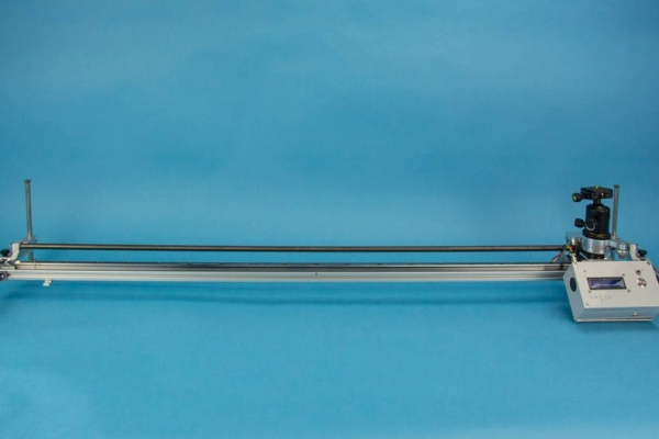
For example when dismantling a machine I found two rails that I could convert into time lapse rails. One rail uses a belt to drive the slider and the other a screw. Pictures in this instructable show a screw driven rail but the same principles apply to a rail driven by a belt. There are just a few parameters that require changing during commissioning.
Step 1: Operating Principle:
For time lapse photography I use a Intervalometer called LRTimelapse Pro-Timer designed by Gunther Wegner. This is a high quality Open Source Intervalometer for time lapse, macro and astro photographers that you can build yourself. Gunther, thank you for this fantastic tool that you have made available to the time lapse community. (For more information see lrtimelapse-pro-timer-free)
I just added some code to control the stepper motor.
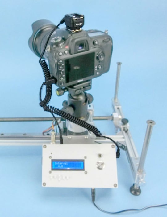
Operating principle: The Time Lapse Rail works on Slave mode. This method is quite reliable. It means that I am using the LRTimelapse Pro-Timer Intervalometer to setup the number of shots and the interval between the shots. The intervalometer sends a signal to the camera to fire the shutter. After a picture is taken the Camera sends a signal back to the motion controller to move the rail’s slider on a Move/Shoot/Move sequence. The signal to start the sequence comes from the camera’s flash hot shoe. The camera’s flash is set to Rear-curtain Synchro, so the signal is sent back to the motion controller when the camera’s curtain closes. This means that the slider will only move when the shutter is closed so will work regardless of exposure length.
Material: Two cables are required from the motion controller to the camera (camera model specific) 1) a Camera Shutter Release Cable with a 2.5 mm Jack and 2) a Hot Shoe Adapter with a Plug to Male Flash PC Sync Cable Cord with a 3.5 mm jack.
Step 2: The Motion Controller’s Board
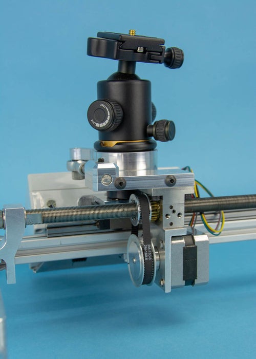
Hardware: Movement of the slider is by means of a screw connected to a NEMA 17 Stepper motor. The stepper motor is driven by an EasyDriver controlled by an Arduino UNO. To use the controller with a different power bank (from 9v to 30v) I added an LM2596 DC-DC Arduino compatible power supply module to adjust the voltage. See the “Arduino Wiring.PDF” attached.
The Camera Shutter Release Cable is plugged in to the controller using a 2.5 mm Jack. The jack is wired according to the schematic found in the attached “Shutter release.PDF”. The Hot Shoe Adapter’s Cable is plugged in to the controller using a 3.5 mm Jack. Having two different sizes avoids plugging a cables to the wrong port.
Step 3: Arduino Code
Before coding it is important to differentiate between the various actions you want to achieve. Arduino allows use of what is called void. A void is a section of program (line of code) that can be called at any time, as and when necessary. So having each action on a separate void keeps the code organised and simplifies coding.
Sketch Logics.pdf attached shows the actions I want to achieve and the logic behind them.
Step 4: Arduino Code 1 – Rail Home Position
The first void is used to send the rail to the Home position when starting the controller.
The controller has a direction toggle switch. On start-up the slider moves in the direction selected by the toggle until it hits the limit switch at the end of the rail; it then moves back by a distance defined by the user (This is 0 or the value that correspond to the opposite end of the rail). This is now the home position for the slider.
This void was tested using the code found in the attached file called BB_Stepper_Rail_ini.txt
Step 5: Arduino Code 2 – Dual Function Push Button
The second void is used to move the slider manually. This is useful when you set up your camera spanning before you start the time-lapse sequence.
The controller has a push button with two functions: 1) a short push (less than a second) moves the slider by a user defined amount. 2) a long push (more than a second) moves the slider to the middle or the end of the rail. Both functions send the slider in the direction selected by the toggle switch.
This void was tested using the code found in the attached file called BB_Dual-function-push-button.txt
Step 6: Arduino Code 3 – Slave Mode
The third void is used to move the slider by a certain amount after each shot. The cameras flash needs setting to “rear curtain”. At the end of the shot a flash signal is sent from the flash hot shoe to the controller. This starts the sequence and moves the slider by a certain amount. The distance for each move is calculated by dividing the length of the rail by the number of shots selected in LRTimelapse Pro-Timer. However a maximum distance can be defined to avoid a fast movement when the number of shots is low.
This void was tested using the code found in the attached file called Slave mode.txt
Step 7: Arduino Code 4 – Quad Ramping
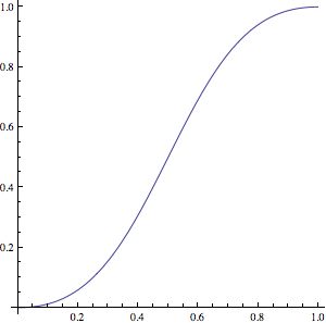
The fourth void is a ramping option for smoother easing in and out. It means the distance of each move will gradually increase up to the set value and at the end of the rail will decrease in the same way. As a result when looking at the final time-lapse sequence the movement of the camera speed up at the beginning of the rail and slow down at the extremity of the rail. A typical Quad acceleration curve is shown in the attached picture (easing in and out). The distance of the ramping can be defined.
I tested the algorithm in Excel and have set-up the acceleration and deceleration curves as per the picture attached. This void was tested using the code found in the attached file called BB_Stepper_Quad-Ramping-calculation.txt
Note: This quad ramping is not to be confused with Bulb ramping where the exposure length changes or Interval ramping where the interval between shots is changed.
Step 8: Arduino Code 5 – Integration With LRTimelapse Pro-Timer
LRTimelapse Pro-Timer is a free Open Source DIY Intervalometer for time-lapse, macro and astro photographers made available to the time-lapse photographer’s community by Gunther Wegner. After building a unit for my camera I found it so good that I started to think about how to drive my rail with it. The attached LRTimelapse Pro-Timer 091_Logics.pdf is a short manual that shows how to navigate the program.
The attached BB_Timelapse_Arduino-code.pdf shows the structure of LRTimelapse Pro-Timer Free 0.91 and in green the lines of code I added to operate the slider.
BB_LRTimelapse_091_VIS.zip contains the Arduino code if you want to have a go.
The attached BB_LRTimer_Modif-Only.txt document lists the additions I have made to Pro-Timer. It makes it easier to integrate them to new versions of Pro-Timer when Gunther makes them available.
Source: Motion Control Slider for Time Lapse Rail