So you saw our video and you’ve fallen in love with Fixbot, have you? That’s okay, it’s understandable. We’ve fallen in love with it too.
We have some great news! You can build your own Fixbot too, provided that you’re okay with getting your hands dirty and that you have access to a Makerbot / RepRap / Ultimaker / 3D printer. You don’t need to be a code wizard or a da Vinci descendant to get through this instructable, but it will help if you know a bit about how to upload sketches to an Arduino.
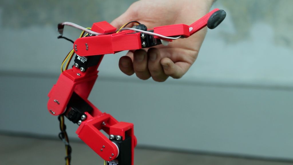
Join us on a journey of bearings, nuts, servos, lots of wires and some ABS, and by the end of it, you’ll have your own Fixbot to play with!
P.S. we’d like to give a hat tip to David Chatting for his trigonometry skills and to Benedikt Gross for his movement learning code!
Step 1: What you’ll need
- 16 x M3, 16mm long bolts and nuts
- 16 x M4, 12mm long bolts and nuts
- 28 x M1.6, 10mm long bolts
- 3 10mm outer diameter x 3mm inner diameter ball bearings
Electronics
- 4 x Hitec HS-422 servos
- 1 x SpringRC SM23/33 microservo (also known as sm-s2309s)
- 1 x Arduino
- 1 x 7.5V DC power supply
Other
- Red, yellow and black solid-core wire
- 3 cable ties
- 2 small terminal blocks
Tools
- M4 allen key
- M3 allen key
- Pliers
- Needle file
- Wire strippers
- Small phillips-head screw driver
- Small flat-head screw driver
Step 2: Print parts
Also, make sure you print one (or all) of the bases for the robot. You have a choice between a vertical screw-mounted base that you can screw onto anything, a GoPro compatible adapter to use with GoPro mounts, or a horizontal screw mounted base.
Step 3: Assemble main chassis
- Bolt one of the servos into part A. This requires four M4 x 12mm bolts and nuts
- Push one of the ball bearings into the bearing hole of a part B
- Screw part B onto the servo wheel. This requires four M1.6 x 12mm bolts and nuts
- Take an M3 x 15mm bolt and pass it through the bearing. Screw it into part A’s hole until it almost reaches the servo on the other side.
- Bolt a new part A onto part B’s M3-sized holes. This requires four M3 x 15mm bolts and nuts. Remember that you have to line them up in the right orientation! The edges of part A and part B should be flush.
Repeat this process of building the chassis until you have mounted 3 servos in total. You have successfully built the robot’s 3 segment arm!
Step 4: Assemble rotation axis
- Bolt part C to the end of the arm (onto the last part A). This requires four M3 x 15mm bolts and nuts. Remember, these holes need to be in the right orientation. Part C should be centered to part A.
- Bolt the last big servo onto part C. This requires four M4 x 12mm bolts and nuts.
Your rotation axis is ready!
Step 5: Assemble finger axis
- Mount part D onto the rotation axis servo’s wheel with four M1.6 x 12mm bolts and nuts.
- Screw the micro servo onto part D with four M1.6 x 12mm bolts.
- Screw the robot’s finger onto the micro servo with a screw that came with one of the Hitec servos.
Fixbot now has a finger!
Step 6: Cable management
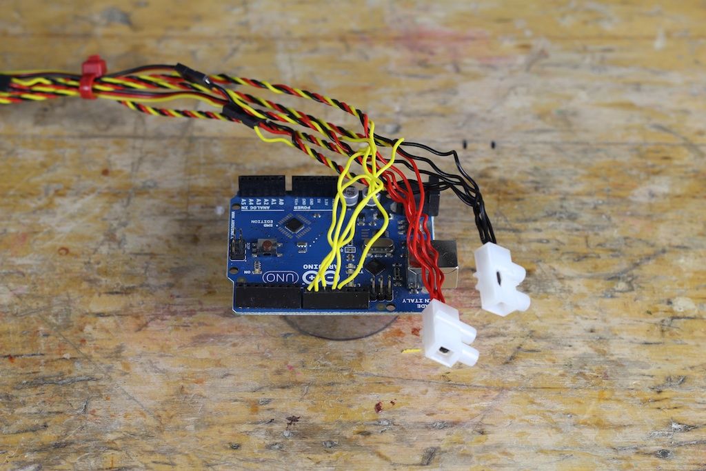
The first thing you want to do is extend the servo cables. You will need 5 cables of different lengths which are progressively shorter. If you want to make your life a bit easier, you could buy servo cable extenders. However, if you don’t wanna fork out extra money, just use some black, red and white solid-core wires.
Coiling the cables
- Take a yellow, a red and a black cable and put them in your battery drill.
- Tighten the chuck so that the cables are held into the drill.
- Hold the other side of the cables and press the trigger! You’ll notice that your cables are coiling neatly into a nice braid.
Cut your braided cables to the 5 different lengths annotated in the picture. Strip both ends of the wires. Plug them into their corresponding servos. The longest cable goes to the finger servo, the shortest goes to the base servo.
Add some cable ties to keep things neat. Make sure you leave some slack for the wires to move around when the robot is moving!