Top hats are cool; just like bow ties. Not only are they stylish, but they give you a lot of room for incorporating techno goodness. I recently had cause to buy a tuxedo, which necessitated a kilt, and then a top hat. You know how it goes. To the tux I added silver buttons, the kilt was exemplary on its own, so only the top hat needed some flash. I decided that since my head is generally in the stars, I should try filling my hat with stars. Initially I was going to use an Arduino and some 1W white LEDs hanging off the PWM lines, and feeding the light through fiber optic lines, to create a twinkling effect. By the time I started work on the project I realized that I wanted colors, and that 1W LEDs were going to drain my LiPo battery pretty darn fast. Multiple color LEDs on a single Arduino is a bit of a problem, though. There are only six PWM channels, so I would max out at two RGB LEDs. Fortunately I had a few sample Total Control Lighting control chips from Cool Neon in my kit, and with a little hacking they are perfect light sources for this project. Each TCL chip is a latching, addressable, three-channel PWM controller; so I can control a near infinite number of RGB LEDs from a single Arduino. Hat space is limited though, so I settled on four; that provided sufficient variety. The end result of my project is a super-stealth techno-mage top hat that looks amazing when it is turned on, and completely normal when it is turned off. I can wear it to Dicken’s Chrismas Fair and nobody will notice, or to That Thing In The Desert where everyone will notice; one hat for all occasions.
I built this project on-site at Burning Man, with only the tools and parts I had in my travel kit. You should be able to complete this project in two days, accounting for glue drying, using easily available parts for less than $200.
tl;dr This article will walk you through every step necessary for adding multi-color dynamic fiber optic lighting to your hat, or any other project to which you want to give a star field effect.

Step 1: Parts
Almost everything used to make this project is ‘off the shelf’. While something may not already be in your toolkit, there isn’t anything here that will be hard to find or for which you won’t be clever enough to make a substitution. 🙂
– Top Hat (Amazon) ($79)
– Optical fibers (I used 156 x .03″ fibers I had in my kit, cut to around 12″) (ebay) (3×1′ = $24)
– 4x Cool Neon TCL controller chips (Not on their website, but $2 w/LED if you call them directly) (4x$2 = $8)
– 4x 8mm RGB common anode LEDs. (Got mine from Cool Neon, paired with the TCL controller chips)
– 2000mAh Lithium Polymer rechargeable battery (Cool Neon / Seeed Studios) ($12)
– LiPo Rider recharging module (Cool Neon / Seeed Studios) ($9.50)
– Seeeduino (Cool Neon / Seeed Studios) ($27)
– 40-pin IDE cable (junk drawer)
– bits of velcro (Home Despot)
– 1/4″ heat-shrink tubing (Fry’s)
– 2x short USB to USB-mini cables
– 3″x2″ piece of cardboard
Cost of major parts (including hat): $159.50
Step 2: Tools
Everything here should be fairly standard. The one item here that will probably need to be substituted out is the hypodermic needle. Threading the fiber optics is a lot easier with a needle that has a dimple in the point, but any large needle should do, with a little extra care.
– Computer with Arduino IDE installed, and internet access to download libraries and code.
– Wire strippers
– Needle nose pliers
– Soldering iron
– adjustable clamp stand
– 28 gauge hypodermic needle (Any thick craft needle will do, but the hollow tip of a hypodermic needle makes it easier to lead the optic fiber back through the hole)
– small paintbrush
– flush-cut wire cutters
– heat gun
– electrical tape
– wood glue (Home Despot)
– Liquid Electrical Tape (Home Despot)
– solder
– masking tape
– zip ties
Step 3: Secure the optical fibers to the LEDs
It’s a bit easier to do this step before the LEDs have been attached to the TCL chips.
– Cut four 2″ pieces of 1/4″ shrink tubing.
– Fit the shrink wrap over the light emitting end of the LEDs. You may need to stretch it out just a little more with the needle nose pliers.
I suggest doing the following steps one LED at a time:
– Pack the open end of the shrink wrap with optical fibers.
– Using the .03″ fibers that I had on hand, this came out to around 40 fibers per LED.
– Heat shrink the tubing around the fibers, and very carefully around the LED as well.
– For extra strength, wrap some electrical tape around the shrink wrap and LED.
-I bound the shrink wrap with zip ties over the LED and the fibers, to provide extra support.
Step 4: Wire up the TCL chips
The key to this project is the TCL controller modules. Without them, I’d be limited to six monochrome LEDs, or two RGB LEDs, because the ‘standard’ Arduino only has six PWM pins. By daisy chaining TCL modules, I can hang a spectacularly large number of RGB LEDs off a mere two pins, leaving me plenty of other input and output pins.
TCL controller modules are four connectors on the front, and four on the back, for communication: Ground, Clock, Data, +5V
These are daisy chained from chip to chip, simply matching the corresponding connections. The order is reversed on the back, but I think the pictures below will be better than a thousand words of explanation.
When bought in quantity they come in a perforated block. I left the chips in a solid four chip strip to minimize footprint.
– Cut a four-conductor strip off a spare IDE cable. I used an old 40-pin cable, because they have wire than the newer 80-pin cables.
– Cut this into one six inch segment, and three two inch segments.
– Strip the ends of all segments back about 1/8 of an inch.
– Solder the six inch segment to the chip side of the TCL module you are designating to be #1 in the series.
– On the reverse side, solder one end of each of the two inch strips to modules number 1, 2 and 3.
– Back to the front, solder the free ends of the two inch strips to modules 2, 3 and 4 on the corresponding pins.
Now that you have the TCL chips daisy chained, with a six inch control lead, we are ready for the LEDs. I mounted my LEDs alternating front, back, front, back; to make running the optical fibers evenly a bit easier.
– Align the cathode pin with the hole marked +5, and the rest of the pins line up.
– Push the leads through the hole as far as you can, solder and cut them.
Step 5: Wire the TCL chips to the controller
Let’s wire up the kit and test it out. I soldered my wiring to the Seeeduino, but you can temporarily use the shield connectors to test.
– Split the ribbon into four separate wires, about two inches from the free end.
Working the wires left to right, as connected to the chip-side of TCL module #1
– connect wire 1, GND, to GND on the Seeeduino
– connect wire 2, clock, to pin 13 on the Seeeduino
– connect wire 3, data, to pin 11 on the Seeeduino
– connect wire 4, +5, to +5 on the Seeeduino
At this point, we should be ready to program and test.
– Download the TCL library and install it into your IDE.
– Download the TopHat sketch, and open it in your IDE.
– Use the IDE to download the TopHat sketch to your Seeeduino.
Once it finishes downloading, the sketch should automatically start, and you will notice that the fiber optic bundles are color cycling.
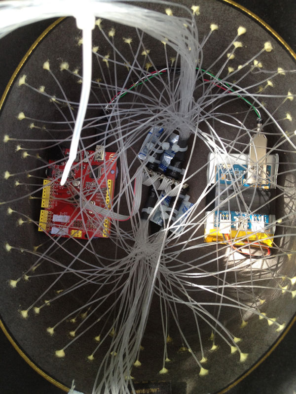
Step 6: Tying the electronics together
The power supply for this project is pretty simple. I taped a LiPo Rider charging module to a 2000mAh Lithium Polymer battery, with a piece of cardboard as an insulator so the solder points on the bottom of the LiPo Rider can not damage the battery casing.
The LiPo Rider is a nifty module. It does USB pass-thru, so you can power and program your Arduino/Seeeduino without disengaging the LiPo Rider. While you are working on your project, the LiPo rider is charging your battery. The LiPo Rider will also accept power from solar cells, for charging. For complete details, check out the LiPo Rider wiki page.
– Cut a piece of cardboard to the size of the LiPo Rider, sandwich between the LiPo Rider and the 2000mAh battery, and secure with electrical tape.
– Connect the Lithium Polymer battery connector to the BATT terminal on the LiPo Rider
– Connect the LiPo Rider and Seeeduino together using a short USB cable
– Flip the LiPo Rider switch to the on position, to verify that your Seeeduino and LEDs are receiving power. Once tested, flip the switch off to conserve power.
For more detail: Make Your Hat With Full Of Stars Using Arduino