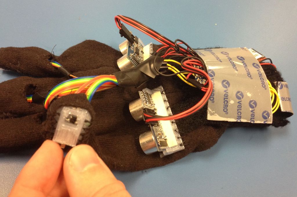
HandSight is a prototype wearable glove that helps blind users detect light/dark surfaces and nearby obstacles. Each finger has an IR reflectance sensor and a vibration motor for tactile feedback; two ultrasonic sensors provide distance and direction cues. The system supports multiple modes and connects via Bluetooth for mode switching and visualization. Built with an Arduino Pro Mini, Bluetooth Mate, and smartphone app, the glove includes 3D-printed sensor housings and sewn attachments for durable, finger-mounted sensor assemblies.
Parts used in the HandSight:
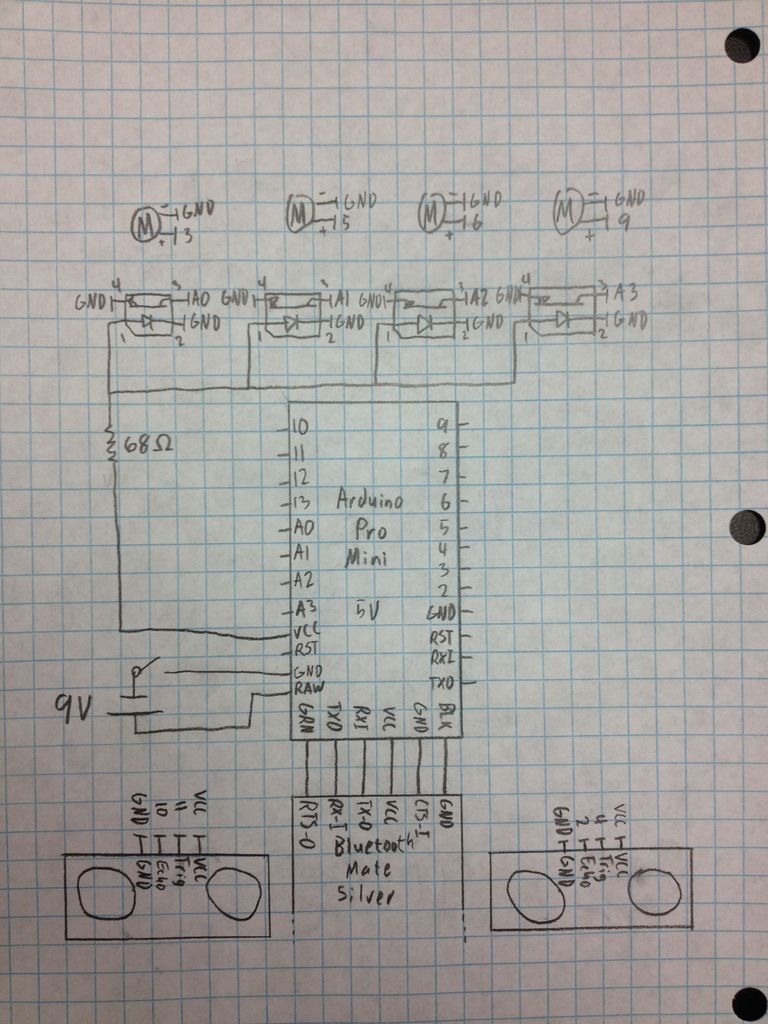
- Arduino Pro Mini-328 (5v)
- IR Reflectance Sensor - QRE1113 (x4)
- Vibration Motor ROB-08449 (x4)
- Ultrasonic Range Finder (HC-SR04) (x2)
- Bluetooth Mate Silver WRL-10393 (x1)
- 68 ohm Resistor (x1)
- 9v Battery and Battery Case with Switch (x1)
- FTDI cable (for programming) (x1)
- Double Sided Sticky Tape or other adhesive
- Wire, electrical tape, soldering materials, rainbow ribbon cable
- Glove for modification
- Extra cloth matching the glove
- Velcro and sewing materials
- 3D printed fingertip and ultrasonic sensor holders (STL files)
HandSight is a prototype glove to aid the blind. It can sense the lightness or darkness of a surface with tactile feedback from a vibration motor for each individual finger. It can also sense distance from physical objects or obstructions and indicate direction and distance with the same vibration feedback. It supports additional modes, and the possibilities are nearly endless. The glove can connect over Bluetooth to switch modes and visualize the sensor readings.
This instructable was made as part of the final project requirement in the CS graduate course “Tangible Interactive Computing” at the University of Maryland, College Park taught by Professor Jon Froehlich. The course focused on exploring the materiality of interactive computing and, in the words of Hiroshii Ishii, sought to “seamlessly couple the dual worlds of bits and atoms.” Please see http://cmsc838f-f12.wikispaces.com/ for more details.
See our Wiki class page for the project here (where we talk about some of our challenges and limitations):
http://cmsc838f-f12.wikispaces.com/HandSigh
 Remove these ads by Signing Up
Step 1: List of Materials
– IR Reflectance Sensor – QRE1113 (x4)
– Vibration Motor ROB-08449 (x4)
– Ultrasonic Range Finder (x2) http://www.amazon.com/Ultrasonic-Module-HC-SR04-Distance-Arduino/dp/B004U8TOE6/ref=sr_1_1?ie=UTF8&qid=1355861471&sr=8-1&keywords=Ultrasonic+Range+Finder
– Bluetooth Mate Silver WRL-10393 (x1)
– 68 ohm Resistor (x1)
– 9v Battery and Battery Case with Switch (x1)
– FTDI cable (for programming) (x1)
– Double Sided Sticky Tape, or other adhesive to hold the ultrasonic sensors in place
– Wire, electrical tape, and soldering materials. Rainbow ribbon cable is recommended for easy wiring of the fingertip sensors.
– Glove that you don’t mind repurposing permanently
– Extra cloth that matches the glove
– Velcro, Sewing Materials
– Windows Phone to run our visualization and control app, or any device that supports the Bluetooth Serial Port Protocol (SPP) if you want to develop your own appAll electronic components available on sparkfun unless otherwise noted
Step 2: 3D Printing
http://www.thingiverse.com/thing:38134We printed with MakerBot Replicator 2. Download STL files, open in a program called ReplicatorG. Put on platform/center. Generate Gcode.Material PLA
Settings used:
infill% 10
layer height 0.27 mm
number of shells 1
feedrate 41 m/s
travel feedrate 56
print temp 226
plastic diameter 1.75 mm
extruder nozzle diameter 0.4mm
(in the actual gcode we changed platform temp to 060, which worked well for PLA)
Print four sets of the fingertip case, and two of the ultrasonic slot.
 ultra_sonic_holder.stl
Step 3: Assembling the IR Sensor Package for Each Finger
Step 4: Attaching Fingertip Assemblies to the Glove
Step 5: Attaching Ultrasonic Sensors to the Glove
- What sensors does HandSight use for fingertip light sensing?
HandSight uses IR reflectance sensors QRE1113 on each fingertip for lightness or darkness sensing. - How does HandSight provide tactile feedback to the user?
Each finger has a vibration motor ROB-08449 that provides tactile feedback based on sensor readings. - What sensors detect distance and obstacles?
Two ultrasonic range finder modules (HC-SR04) detect distance and help indicate direction and distance. - How are the sensors mounted to the glove?
Fingertip assemblies are placed in 3D-printed holders cut into the glove fingertips, and ultrasonic sensors are sewn and adhered to the top of the glove. - Can the glove communicate with external devices?
Yes, HandSight uses a Bluetooth Mate Silver WRL-10393 to connect over Bluetooth for mode switching and visualization. - What microcontroller runs the HandSight system?
An Arduino Pro Mini-328 (5v) is used as the microcontroller for the project. - Is 3D printing required for building the sensor housings?
Yes, the project uses 3D-printed fingertip cases and ultrasonic sensor holders; STL files are provided. - What power source does HandSight use?
The project uses a 9v battery and battery case with a switch as its power source. - What additional tools and materials are needed for assembly?
Soldering materials, wire, electrical tape, double sided tape, sewing materials, and optionally a rainbow ribbon cable are required.